FA168CPS / FA168CPSSIA FA168CPSSIA FA148CP / FA148CPSIA Security Systems Programming Guide ARMED READY R A B 2 AWAY 1 OFF 4 5TEST MAX T C 7INSTAN READY 8 CODE 0 3STAY 6BYPASS 9 CHIME # D FA 26 0 ARMED ON READY OFF R AWAY STAY 1 OFF 4 MAX 7INSTANT PAGE READY 2 AWAY 5 TEST 8 CODE 0 FA 5 6 0 K5305-5PRV5 11/08 Rev.
TABLE OF CONTENTS PROGRAMMING MODE COMMANDS.....................................................................................................................3 DATA FIELD PROGRAMMING FORM .....................................................................................................................4 CONFIGURABLE ZONE TYPES WORKSHEETS..................................................................................................17 ∗56 ZONE PROGRAMMING MENU MODE......................................
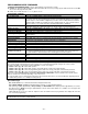
PROGRAMMING MODE COMMANDS TO ENTER PROGRAMMING MODE (using an alpha keypad connected to the control): A. POWER UP, then press [✱] and [#] at the same time, within 50 seconds of powering up (this method must be used if ✱98 was used to exit program mode). OR B. Initially, key: Installer Code (4 + 1 + 1 + 2) plus 8 + 0 + 0. PROGRAMMING COMMANDS Task Go to a Data Field Entering Data Command/Explanation Press [∗ ∗] + [Field Number], followed by the required entry.
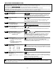
DATA FIELD PROGRAMMING FORM Entries apply to the FA168CPS/FA168CPSSIA and FA148CP/FA148CPSIA controls, except entries shown in dashed boxes, which apply only to the FA168CPS/FA168CPSSIA (partition entries) and are not applicable to the FA148CP/FA148CPSIA controls. SIA-Compliant Controls: Where noted, certain fields have special settings when used with the FA168CPSSIA and FA148CPSIA SIA-Compliant controls (indicated by SIA-Compliant Controls in reverse type and heavy borders for easy identification).
∗31 Single Alarm Sounding Per Zone 0 = unlimited sounding 1 = one alarm sounding per zone [0] If enabled, limits alarm sounding on the bell output to once per zone per armed period. SIA-Compliant Controls: If “0” selected, “alarm sounding per zone” will be the same as the “number of reports in armed period” set in field *93 (1 if one report, 2 if 2 reports, unlimited for zones in zone list 7).
∗39 When the system powers up armed, an alarm will occur 1 minute after arming if a zone is faulted. Note that if the previous state was armed Away or Stay, the system ignores sensor changes for 1 minute, which allows sensors such as PIRs to stabilize. UL: must be 1 SIA Guidelines: must be 1 Power Up In Previous State 0 = no, always power up disarmed; 1 = yes, power up in previous state SIA-Compliant Controls: Feature always enabled; field does not exist.
∗50 Burglary Dialer Delay Delay Time: 0 = no delay 1 = 15 seconds 2 = 30 seconds 3 = 45 seconds SIA-Compliant Controls: Delay Time: 1 = 15 seconds 2 = 30 seconds 3 = 45 seconds Delay Disable: 0 = use delay set in entry 1 1 = dial delay disabled for zones listed in zone list 6 (use zone list 6 to enter those zones that require dial delay to be disabled; these zones ignore the setting in entry 1) [2,0] Delay Time SIA-Compliant Controls: Delay Disable Provides delay of “BURGLARY ALARM” report to the centra
TO PROGRAM SYSTEM STATUS, & RESTORE REPORT CODES (∗ ∗59 thru ∗68, *70 thru ∗76, and ∗89): For 3+1 or 4+1 Standard Format: Enter a code in the first box: 1–9, #+10 for 0, #+11 for B, #+12 for C, #+13 for D, #+14 for E, #+15 for F. A 0 (not #+10) in the first box disables a report. A 0 (not #+10) in the second box results in advance to the next field. For Expanded or 4+2 Format: Enter codes in both boxes (1st and 2nd digits) for 1–9, 0, or B–F, as described above.
∗66 Arm Away/Stay Rpt Code See above for entries. [0,0,0,0,0,0] Away Stay Part. 1 Away Stay Part. 2 Away Stay Common This option allows for independent programming of Away and Stay reports for each partition, including the common lobby. NOTE: “OPEN” reports are not sent if the associated closing report is not enabled. ∗67 RF Trans. Low Bat Report Code See above for entries. | [00] Sent when a transmitter low-battery condition exists.
OUTPUT AND SYSTEM SETUP (✱77 – ✱93) Daylight Savings Time Start/End ∗77 Month 0 = Disabled 1-9 = January-September (1 = Jan, 2 = Feb, etc) #+10 = October #+11 = November #+12 = December ∗78 Daylight Savings Time Start/End Weekend 0 = disabled 1 = first 2 = second 3 = third 4 = fourth 5 = last 6 = next to last 7 = third to last | [3][11] Enter the start and end month for daylight savings time, if applicable to the region.
∗88 ∗89 ∗90 ∗91 Program Mode Lockout Options 0 = standard *98 installer code lockout (reentry only by [∗] + [#] within 50 secs after power up) 1 = lockout [∗] + [#] reentry after *98 exit (reenter via installer code or downloader only) 2 = not applicable (option doesn’t exist) 3 = lockout local programming after *98 exit (reenter by downloader only) This table summarizes the Program Mode Lockout options: Exit *88 Reentry By: Command Entry Installer Power-up† *99 n/a yes yes *98 0 no yes *98 1 yes no *9
∗93 Reports In Armed Period Per Zone (Swinger Suppression) Restrict Report Pairs: 0 = Unlimited Reports 1 = 1 report pair per zone per armed period 2 = 2 report pairs per zone per armed period [1,0] Restrict SIA-Compliant Controls: Report Pairs Unlimited Reports Enable Selection limits the number of alarm/alarm restore message pairs per zone sent to the CS in an armed period. Swinger suppression applies to burglary zones only.
∗160 ∗161 ∗162 ∗163 ∗164 ∗165 Pager 1 Phone No. Enter up to 20 digits. 0–9 #+11 = '✱' #+12 = '#' #+13 = 2-second pause | Pager 1 Characters Enter the optional prefix characters, up to 16 digits.
∗171 ∗172 Pager 4 Report Options See field *162 for reporting options. Select for each partition (use zone list 12 for options 12 or 13). Pager Delay Option For Alarms 0 = none 1 = 1 minute 2 = 2 minutes 3 = 3 minutes [0,0,0] P2 comm P1 [3] This field determines the delay of alarm reports to the pager. This gives the Central Station enough time to verify the alarm report it received before the dialer attempts to dial the pager. This delay is for ALL pagers in the system.
∗182 Configurable Zone Type 90 (0-9, #+10=10, #+11=11, #+12=12, #+13=13, #+14=14, #+15=15). 1 2 3 4 5 6 7 8 9 10 Enter the appropriate value for each entry, 1-10, based on the charts provided in the Configurable Zone Type Worksheet section. Each entry is the sum of the values of its selected options To calculate the value for each entry, add the values of the selected options in each of the entry’s columns shown in the respective chart (one option per column).
KEYPAD OPTIONS *190-*199 To enable keypads: 1. Set desired address at keypad (refer to keypad’s instructions for setting the address). 2. Use data fields *190-*196 to enable keypad addresses, assign a partition, enable sound options in field. 3. Use fields *197, *198, and *199 to turn on partition number display, exit time interval display, and select fail display mode. 4. Set keypad-related data fields as appropriate: *21 Quick Arm Enable, *23 Forced Bypass, *84 Auto STAY Arm NOTES: 1.
CONFIGURABLE ZONE TYPES WORKSHEETS Configurable zone types 90 and 91 can be programmed via downloader software or from a keypad using data fields*182-*185. Configurable zone types 92 and 93 (FA168CPS only) can only be programmed using the downloader software. Programming Configurable Zone Type options involves making 10 entries in data field *182 for zone type 90 and field *184 for zone type 91, where each entry represents the sum of the values of the various options shown in the tables below.
∗56 ZONE PROGRAMMING MENU MODE (press *56 while in Program mode) The Zone Programming Worksheet is on page 36. Zones and Partitions Each protection zone needs to be programmed with various attributes using *56 Zone Programming mode or ✱58 Expert Programming Mode. Using this mode, enter the zone number to be programmed and make appropriate entries at the prompts. Finally, Confirm the serial number of wireless transmitter zones.
10 Report Code 1st 01 2nd 00 Report Code (RC) 10 First Digit: 1-9, 10 for 0, 11 for B, 12 for C, 13 for D, 14 for E, 15 for F 00 to disable Second Digit: same as above [∗] to continue 02 HARDWIRE TYPE EOL 0 Hardwire Type 0 = EOL 1 = NC 2 = NO 3 = zone doubling (ZD) †; 4 = double-balanced (DB)† [∗] to continue Response Time (RT) 02 Response Time 1 10 INPUT TYPE RF TRANS 3 10 INPUT S/N: L A022-4064 1 0 = 10mSec; 1 = 350mSec 2 = 700mSec 3 = 1.
10 INPUT S/N A022-4064 L ? XMIT TO CONFIRM PRESS ✱ TO SKIP Entd A022-4063 1 Rcvd A022-4064 1 Loop Number Change [∗] to continue Confirmation Option [∗] to continue If Serial or Loop Numbers do not match after activating the transmitter [∗] to continue 10 INPUT S/N: A000-0000 L 0 Zn ZT RC In: L 10 03 10 RF: 1s PROGRAM ALPHA? 0 = NO 1 = YES 0 E N TE R Z N N U M. ( 0 0 = Q U I T) 1 1 To Delete a Serial No.
Zn ZT P RC IN: L 10 00 1 10 RF 1 Zone Programming ZT = see Zone Type chart shown in *56 Menu Mode “Zone Type” prompt P = partition 1, 2, 3 (common); RC = 1 (send CID report); 0 (no report) IN = input type; L = loop number [∗] to continue A summary screen with the selected zone’s current programming appears.
• Confirm XMIT TO CONFIRM PRESS ✱ TO SKIP [∗] to continue IMPORTANT: When confirmed, the key is not active for arming/disarming until it is assigned to a user number (using the assigning attributes command, attribute “4”). See System Operation section for procedure. If the serial number transmitted does not match the serial number entered, a display similar to the one shown will appear. If the loop number does not match, it will also be displayed.
∗57 FUNCTION KEY PROGRAMMING MENU MODE (press ∗57 while in Data Programming mode). The system provides the ability to program each of the four keypad function keys to perform one of 12 system operations. The end user can then activate the function by simply pressing and holding the programmed key for 2 seconds. Typical functions (listed below) include single-button arming, turning lights on/off, or single-button paging.
OUTPUT DEVICE PROGRAMMING GENERAL INFORMATION (*79/*80 Menu Mode) Output Devices: The FA168CPS system supports up to 16 relays and/or Powerline Carrier devices (X-10 devices) plus 2 built-in trigger outputs in any combination. These 18 “outputs” are assigned to system-wide output numbers (01-18). Use *79 Menu Mode to assign output numbers and map them to device addresses. The FA148CP supports 8 relays and 2 built-in trigger outputs (total 10 outputs).
XX OUTPUT TYPE DELETE 0 Output Type 0 = delete 1 = relay on 4204/4229 module 2 = Powerline Carrier device (X-10) [∗] to continue “A” Unit Number XX UNIT No. 01-16 = predefined address [∗] to continue yy “B” XX MODULE ADDR 07-15 yy Module Address 07-15 = predefined address [∗] to continue Select whether this is a relay or a Powerline Carrier (X-10) device. If Powerline Carrier is selected, go to “A” prompt. If relay is selected, skip to “B” prompt.
80 Menu Mode Output Funct. # (00 = Quit) 01 01 A E P Trig ?00 0 0 – ZL=00 Output Function No.
“C” Zone Number Press [✱] to continue. 01 Enter Zn No. 12 01 Output Action Close for 2 sec 1 Enter Output No. R02 02 02 A E P TRIG R02 1 1 3 ZL=00 Output Action (prompt appears if zone number was selected) Enter the desired zone number associated with this output number. At the ENTER EVENT prompt, enter the zone event that will activate this output. 01 Enter Event 0 = restore; 1 = alarm/fault/trouble Restore 0 Press [✱] to continue to the “Output Action” prompt Enter the desired device action.
01 Delete Zone? 0 = No 1 = Yes Deleting a Zone 0 01 Zn to Delete? (00 = Quit) 00 0 = don’t delete zones 1 = go to next prompt to delete zones [∗] to continue Delete the Zone 01-64† = zones to be deleted from list followed by [∗] to accept each zone 00 to continue To save the zone list, enter 0 and the system returns to the Zone List No. prompt. To delete a zone or zones in a zone list, enter 1 to continue. Enter each zone to be deleted from the list, followed by [✱].
EXAMPLE: (a) ✱ ZN 01 (b) ✱ ZN 01 Descriptor Example EXAMPLE: “BACK DOOR” a. From the list, BACK = 013, so, after entering the zone number to be edited (step 1), enter #013. If you accidentally enter the wrong word, simply press [#] plus the correct 3-digit number for the word you want. b. Press [6] to accept the selected word and continue to the next word. (if this is the only word you are using for the descriptor press [8] to save it). c.
ALPHA VOCABULARY LIST (For Entering Zone Descriptors) 000 • 001 • 002 004 005 • 006 • 007 • 009 010 • • • • • • • 012 013 014 016 017 018 019 020 • 021 • 022 023 025 • 026 028 • 029 030 031 033 034 035 036 • 037 038 • 040 • 046 047 • 048 049 • 050 051 • 052 • 053 054 055 Note: (Word Space) –A– AIR ALARM ∗ ALLEY AMBUSH AREA APARTMENT ATTIC ∗ AUDIO –B– BABY ∗ BACK ∗ BAR BASEMENT ∗ BATHROOM ∗ BED BEDROOM ∗ BELL BLOWER BOILER BOTTOM BREAK BUILDING –C– CABINET CALL CAMERA CAR CASH CCTV CEILING CELLAR CENTRAL
SETTING SCHEDULES (Installer Code + [#] + [6] [4]) The system provides schedules, which can be used to automatically control 11 types of system events at pre-defined times. Some events are reserved for the installer only. FA168CPS: Provides up to 32 schedules: 16 schedules for use by the end-user, 16 for use by the installer. FA148CP: Provides up to 8 schedules: 4 schedules for use by the end user, 4 for use by the installer.
REPEAT OPTION 0-4 X 0 = do not repeat 1 = repeat weekly 2 = repeat biweekly (every other week) 3 = repeat every third week 4 = repeat every fourth week Press [∗] to continue. Randomize RANDOMIZE 0=NO 1=YES Repeat Option X 0 = no 1 = yes Press [∗] to continue and return to ENTER SCHED NO. prompt to program the next schedule. Enter the desired repeat option for this schedule. e.g., To make a schedule that happens everyday you would select all days with a repeat count of 1.
∗29 COMMUNICATION DEVICE MENU MODE (Pass-Through Programming) This mode is for programming an IP, GSM, or IP/GSM Communicator Module using an alpha keypad. Alternatively, these options can be programmed via the AlarmNet Direct website. After programming is complete, the module must be registered with AlarmNet before reporting via the communication device can occur. Refer to the device’s instructions for registration procedures. NOTE: The module must be set to device address 3.
ZONE TYPE DEFINITIONS Zone types define the way in which the system responds to faults in each zone. Type 00 Zone Not Used Program a zone with this zone type if the zone is not used. Type 01 Entry/Exit Burglary #1 • Assign to zones that are used for primary entry and exit. • Provides entry delay when zone is faulted if control is armed in the Away, Stay, or Night-Stay modes. • No entry delay provided when the panel is armed in the Instant/Maximum mode.
UL NOTICES 1. Entry Delay No. 1 and No. 2 (fields ∗35, ∗36) cannot be greater than 30 seconds for UL Residential Burglar Alarm installations, and entry delay plus dial delay should not exceed 1 minute. For UL Commercial Burglar Alarm installations, total entry delay may not exceed 45 seconds. 2. For UL Commercial Burglar Alarm and UL Residential Burglar Alarm installations with line security, total exit delay time must not exceed 60 seconds. 3.
WORKSHEET FOR ∗56 ZONE PROGRAMMING (FA148CP supports up to 32 zones: 1-6, 9-34, 49-56) [default shown in brackets] Zone 1 2 3 4 5 6 7 8 Zone NOTES: Zone Type: see chart in ∗56 Zone Programming Menu mode section. Report Code: enabled if any digit entered as 1st digit; Hardwire Type (zns 2-8): 0 = EOL 3 = ZD 1 = NC 4 = DB 2 = NO Input Type: 2 = AW (zones 9-48) 3 = RF (zones 9-48) 4 = UR (zones 9-48) 5 = BR (zones 49-64) NOTE: Zones 9-16 not available if zone doubling enabled.
WORKSHEET FOR ∗57 FUNCTION KEY PROGRAMMING Option 01 02 03 04 05 06 07 08 09 10 11 12 00 Function A B C D Comments Paging Time Display Arm AWAY Arm STAY Arm NIGHT-STAY Step Arming Device Activation Device: Comm.
WORKSHEET FOR ∗80 OUTPUT FUNCTION PROGRAMMING Fill in the required data on the worksheet below and follow the programming procedure in the installation manual as you enter the data during the displays and prompts that appear in sequence. Notes: 1. For Relays, 4229 and 4204 devices are programmed in *79, *80, and *81 modes. 2. For Powerline Carrier devices (plcd), field ✱27 must be programmed with a House Code. 3. Tampers of expansion units cannot be used to operate devices.
WORKSHEET FOR SCHEDULES (installer code + [#] + [6] [4]; master code can only access schedules 01-16 for FA168CPS, 01-04 for FA148CP, and events 00-07 for both controls; FA148CP supports up to 8 schedules, FA168CPS supports up to 32 schedules ) No. Event Device No. Group No.
5800 SERIES TRANSMITTER INPUT LOOP IDENTIFICATION All of the transmitters illustrated have one or more unique factory assigned input (loop) ID numbers. Each of the inputs requires its own programming zone (e.g., a 5804's four inputs require four programming zones). For information on any transmitter not shown, refer to the instructions accompanying that transmitter for details regarding loop numbers, etc.