BRK Series H.264 Digital DVR , user S manual MODEL PRO-D1610 16 Channel DVR 1.0TB H.
introduction thank you Welcome Thank you for choosing First Alert for your security needs! For more than half a century, First Alert has made the home-safety and security products that make your job easier. Our products are built to the highest standard which has earned us a leadership role in the home-safety and security product categories. We are committed to serving our customers, from the professionals who install our products, to the families and businesses who count on them.
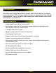
introduction key product features Main Description Sixteen channel H.264 digital video recorder with Internet remote surveillance, motion detection, PTZ and alarm control suitable for applications such as highend residential - new or remodel, light commercial, small business/retail, small warehouse or small grocery. Product features • H.
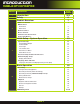
introduction table of contents Page number section description 1 2 Introduction Safety Product Overview 2-3 6 7 What is in the Box 7 DVR Controls 3 Front Panel 8 Back Panel 9 Remote Control 10 Mouse Controls 11 Camera Power Connections 12 Connecting Devices 12 Initial Setup - System Operation System Start Up 4 13 Default Video Output 13 Power On/Off 13 User Login 13 Live View Screen 14 Quick Access Menu 14 Main Menu Access 14 Password Setup and User Permissions 15 Camera
introduction table of contents Page number section description Advanced Operation 22 Alarm 22-23 Alarm Setup 22-23 E-mail Setup 23 System Info and System Update 6 24 System Maintain 24 Upgrade Firmware 24 PTZ Setup and Control 25-26 Step 1: Connect your PTZ Camera to this DVR 25 Step 2: Configure PTZ Communication Settings 25 Step 3: Configure the Operation and Control of your PTZ Camera(s) 25 Step 4: Configure the CRUISE SETTING of your PTZ Camera 26 Remote Access 27 Network Se
safety caution statements safety precautions • • • • • • Do not drop, puncture, or disassemble the DVR. Do not tug on the power adapter. Use the plug to remove it from the wall. Do not expose the DVR to high temperatures. For your own safety, avoid using the DVR when there is a storm or lightning in your area. Use the DVR with care. Avoid pressing hard on the DVR body. Do not crush or damage the power cable.
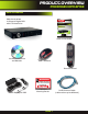
product overview package contents , What s in the box PRO-D1610 H.264 16 Channel Digital DVR with 1TB Hard Drive BRK Series H.264 Digital DVR quick install guide MODELS PRO-D1610 16 Channel 1.0TB H.264 VIDEO COMPRESSION DIGITAL DVR RECORDER MOBILE PHONE/ WEB READY DVR OPTIMIZED SATA HDD Quick Install Guide Installation Software and Manuals USB 2.
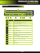
product overview dvr controls Front Panel 4 6 3 2 7 Item Function 5 Control 8 1 Description 1 Standby Press to enter/exit standby mode 2 IR Sensor IR receiver for the remote control 3 MENU/EXIT Press to open/close the main menu 4 LED Indicators Shows status of Link, 100M, Full, Alarm, Record, HDD. 5 Channel Numbers Press buttons 1~9 to view the selected channel in full-screen. To display 2-digit channels press both buttons slowly.
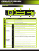
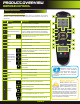
product overview dvr controls back Panel 10 8 1 3 Item 2 5 6 7 4 9 Function Description 1 POWER Input DC 12V/3A power connection 2 Network For connecting RJ45 ethernet cable to PC or router 3 VGA Output For connecting to a VGA monitor 4 Video Output For connecting to a BNC monitor (800 x 600) - NTSC or PAL Alarm Input 4 alarm inputs Alarm Output 2 alarm outputs RS485 For connecting PTZ cameras +12V Power supply for alarm block inputs, the current is 100mA (to prevent short
product overview remote control remote control Remote Control Operation The remote control is the secondary input device for navigating the system’s interface. In device operation, the OK key has the same function as “left click” of the mouse. Item 2 1 Function Description 1 STANDBY Press to turn standby mode ON/OFF 2 LOGIN/LOCK If “Security” has been enabled in the setup menu, press to open the user password login screen or log off system.
pRODUCT oVERVIEW MOUSE and virtual Keypad MOUSE controls Mouse Operation with this DVR The mouse is the primary input device for navigating system menus. NOTE: Unless otherwise noted, all system functions described in this manual are achieved through mouse input. To use a mouse with the system: Connect a USB mouse to the USB MOUSE port on front panel of the system. NOTE: Only the USB 2.0 port on the front panel is designed for data backup to a USB flash drive.
product overview cAMERA AND pOWER cONNECTIONS connecting devices Follow this diagram to make device connections. This diagram is for illustration purposes only. Cabling and other accessories shown are not included with this DVR unless indicated. See “What’s in the Box” for included devices. DVR Front Face Connect Mouse & USB Drive Powering Cameras Powering Cameras Power from a single Power Adaptor and 8-way splitter. 2 required. Not included.
initial setup system operation system start up Default Video Output The default video output for the DVR system is VGA. If you connect a BNC (CVBS) monitor on initial setup, you will need to use the mouse “Scroll Wheel” to switch to the BNC output to be able to use the mouse. Roll the mouse “Scroll Wheel” backward to go to BNC and forward to go to VGA. The REMARK screen is shown on startup.
initial setup system operation Live View Screen The Live View Screen is the home or main viewing screen. It shows live video of all current cameras connected to the DVR. You can double-click a channel at any time to view it in single-channel mode. You access all menus from this Live View screen via the Quick Access Menu. You will also see the Channel number or name, time and day information (see page 16 “Camera Display Setup” for customizing the Live View Screen).
initial setup system operation Password Setup Setting Up Passwords & User Permissions When you first startup your DVR, you are automatically logged in as the ADMIN under Device ID: 000000. By default, passwords are disabled on the system. You will not need a password to log in or access menus. You will not need a password to access your system using the browser-based remote software. The system employs two levels of user authorities connected to a Device ID. The levels are as follows: 1.
initial setup system operation camera display setup Setting Up Cameras for Viewing and Recording Use the Display Setup menu to customize channel titles, show/hide the date and time in live viewing and playback, and enable/ disable preview channels. To customize Display settings, click DISPLAY from the Main Menu: Display 1.
initial setup system operation System Setup Use the SYSTEM SETUP Menu to set the system language, date and time, device IDs and passwords, system maintenance, configure video settings and gather system information like serial number and software version. language, date and time Setting Up Language/Date/Time Set the system language, date and time, passwords, and configure video options. Language To change the system language:, from the drop-down menu select LANGUAGE. Click APPLY.
Basic Operation Recording recording RECORD Mode Configure Recording Options: In this Menu you have three recording options: POWER UP (Continuous), TIMER RECORD (enables SCHEDULE menu) and ALARM (within SCHEDULE menu). By default, the DVR is set to record continuously. Set parameters as follows: 1. From the Main Menu click RECORD. Under SWITCH, use the drop-down menus and select ON/OFF to enable/disable recording from the selected channel.
Basic Operation Recording Recording Schedule (TIMER RECORD) Example You want your system to record continuously on all channels from 9 AM to 5 PM Monday to Friday. You also want Alarm/Motion recording from 5 PM to 9 AM. You do not want the system to record Saturday or Sunday: 1. Open the Schedule menu. 2. Under CHANNEL, select ALL. 3. Click the blue NO RECORD block below the grid. A checkmark will appear in the block. 4. Under SUN, click blocks 00~23. The blocks will turn blue. 5. Under FROM, select SUN.
Basic Operation Playback playback PLAYBACK Mode Playback and Record Search View recorded video on the system through the SEARCH Menu. To begin playback: 1. There are two ways to access the SEARCH menu. Right-click anywhere on the screen and select VIDEO SEARCH from the Quick Access Menu. The SEARCH Menu opens. Or from the Main Menu select SEARCH. NOTE: When you first open the SEARCH Menu, it displays the current month and date. 2. Click PLAYBACK to select a specific channel.
Basic Operation Playback Backup Use the FILE LIST sub-menu to find recorded video on your system and copy it to a USB flash drive (not included). NOTE: The system is compatible with most major brands of USB flash drives, with capacities from 256 MB to 4 GB. To backup recorded data: 1. Connect a blank USB flash drive to the top USB port on the front panel of the system. 2. Open the FILE LIST menu and search for recorded data on the system as shown above. 3.
ADVANCED Operation ALARM Hard Drive and USB Options continued: Formatting the USB Flash Drive Use a USB flash drive to backup recorded video and upgrade the system`s firmware. You should always format the USB flash drive you intend to use with the system. NOTE: Not formatting the USB flash drive may result in improper functionality. USB Flash Drives The system is compatible with most major brands of USB flash drives, with capacities from 256 MB to 4 GB.
Advanced Operation ALarm 4. Click APPLY. Click OK in the confirmation window. Alarm Inputs: Alarm inputs are devices or switches that activate when a door, window, cabinet etc. is opened or accessed. For example, you might want to only have the camera record when someone opens a tool cabinet or when a door opens vs. recording when motion occurs around those areas. There may be people moving by those areas frequently but you are only concerned about when those areas are accessed.
Advanced Operation System System Info and System Update System Information: View system information, including the serial number, software version, MCU and MAC address, and serial number of the system. To access this menu, from the MAIN MENU click SYSTEM then click INFO. System Maintain Use the SYSTEM MAINTAIN menu to update system firmware and set an automatic system reset schedule. To access this menu, from the MAIN MENU click SYSTEM then click MAINTAIN.
Advanced Operation PTZ Pan tilt zoom...PTZ PTZ Inputs Configuration Pan/Tilt/Zoom (PTZ) Setup: ALM IN Install 120 Ω terminating resistor in last camera only A ~ ~ Step 1: Connect your PTZ Camera to this DVR Connect a PTZ camera to the BNC and DC power cables. Also, connect the communication cable from the PTZ camera to the 485A (TX, +) and 485B (RX, -) control inputs to the Alarm/PTZ block on the back of the DVR. Note there are two sets of PTZ control connections (485A-1/485B-1 & 485A-2/485B-2).
Advanced Operation PTZ Setup Pan/Tilt/Zoom (PTZ) Setup Continued: In the PTZ SETUP screen you can set or control the following for each PRESET defined: 1. SET PRESET: Saves any PRESET functions changed with this screen. 2. CLEAN PRESET: Clears a defined PRESET without going to the SET CRUISE screen. 3. CALL PRESET: Calls a defined PRESET without going to the SET CRUISE screen. 4. AUTO SCAN: Enables AUTO SCAN feature without going through Quick Access Menu. 5.
REMOTE Access Network Setup Network Setup for Remote Access Use the NETWORK SETUP menu to configure your network and DNS settings for remote access. If you are only going to access the DVR locally from a computer attached to the same router as the DVR, you only need to configure settings using either the DHCP or STATIC IP. Because you are on the same network, port forwarding and knowing the public IP address are not necessary.
REMOTE Access Network Setup To configure Static IP settings in the DVR: 1. Select STATIC IP from the TYPE drop down box in the NETWORK SETUP Menu. 2. Enter your IP Address, Subnet mask, and Gateway info you obtained from your computer through the previous step in the respective fields using the Virtual Keyboard. 3. Click APPLY. Click OK in the confirmation window. 4.
Remote Access Network Setup DDNS (Dynamic Domain Name Service) A DDNS account allows you to set up a web site address that points back to your Local Network so you can access the DVR over the Internet using a static or dynamic IP address. One problem with a dynamic address is your internet service provider (ISP) changes this address from time to time. When it changes you need to re-configure your DVR with the new address. To do so you will have to get the new IP address. Although you can go to www.
REMOTE Access Network Setup Next configure DDNS settings in the DVR From the Network Setup menu, enter Primary or Secondary DNS from the WAN settings of your router in the DNS field 1. Click DDNS SETTINGS. 2. Under DDNS, select ON. 3. Under SERVICE, select DYNDNS if you obtained your domain name from DynDNS.com. 4. Under DOMAIN NAME, enter your DDNS domain name you received from the confirmation email. For example, if your domain name is adam@ dyndns.com, you need to enter adam@dyndns.
REMOTE Access Remote Surveillance Remote Surveillance Remote Surveillance using Internet Explorer 8 or 9: The DVR features built-in browser-based software that allows you to access your system remotely over your local area network (LAN) or over the Internet using Internet Explorer®.
REMOTE Access Remote Surveillance Configuring ActiveX Control in Internet Explorer 8: 1. Open Internet Explorer 8 2. Click on Tools 3. Select Internet Options in the pull-down menu 4. Click on the Security Tab 5. Select Trusted Sites 6. Click on the Sites button 7. Uncheck the “Require server verification (https:) for all sites in this zone” button. 8. Type the DVR’s IP address (obtained during Network Setup) or DDNS domain name (obtained through DynDNS.
REMOTE Access Remote Surveillance Remote Surveillance Main Screen: Upon login, the Remote Surveillance main screen appears in your browser. 1 4 3 5 2 7 Item 6 8 Function Description 1 Modes Click LIVE, PLAYBACK, and SETUP 2 Main Screen Main display screen for live viewing and playback 3 Time Stamp Time stamp appears on each channel 4 Channel Channel number appears in the top left corner 5 PTZ Control PTZ control for any connected PTZ cameras (not included).
REMOTE Access Remote Surveillance Live Viewing Tab: By default, Remote Surveillance opens in Live Viewing mode (split-screen). To use Live Viewing: 1. Click LIVE at the top of the main screen. 2. Click the display mode icons to view the main screen in single-channel, quad, or split-screen configurations. You can also double-click a channel at any time to view it in single-channel. 3. Click to show or hide all the channel windows. 4. 5. Click to start/stop manual recording to your PC on ALL channels.
REMOTE Access Remote Surveillance Playback Tab Use the Replay menu to search and playback recorded video on your system. Remote Viewing-Playback Screen To use the replay menu: 1. Click REPLAY at the top of the main screen. The main screen will be grey. 2. Click REFRESH below the calendar to view the recorded files for the current month. NOTE: Normal recording is indicated by a clock icon; alarm recording (alarm, loss, and motion events) are indicated by an exclamation mark icon. 3.
REMOTE Access Remote Surveillance Search Use the calendar and drop-down menus to search for recorded video on your system. 1. Click < > to change the month on the calendar. Dates with recorded video data will appear in bold. 2. Click the date. Recorded video files will populate the File List. 3. From the Channel drop-down menu, select a specific channel or select ALL CHANNEL and then click SEARCH. 4. From the Type drop-down menu, select COMMON (normal recording), ALARM, or ALL TYPE and then click SEARCH.
REMOTE Access Remote Surveillance Setup Tab Use the SETUP tab to configure the settings of your system from a remote location. NOTE: If the Main Menu is open on the system, you will not be able to make changes to the system from the remote location. To open remote setup: Click SETUP at the top of the main screen.
REMOTE Access Remote Surveillance SETTING You can check and change the parameter settings as configured in the DVR 1. BANDWIDTH: Set the bandwidth in kbps (128k, 192k, 256k, 384k, 512k, 1024k) that you want to allocate for traffic based on internet bandwidth available. This bandwidth does not include audio. 2. FILE SAVE PATH: The path where you want to save captured picture and recording video.
Mobile Phone Setup and Control Mobile Phone Mobile Setup Mobile Setup allows you to send alerts to your cellular phone running Windows Mobile Pro, Android, Blackberry, or iPhone on 3G networks. To get the latest software it is recommended that from your phone you go to your App Store or Market icon and search for the MEye application. Step1: Configure DVR - For all phones configure MOBILE settings as follows: 1. From the MAIN Menu click ADVANCED then MOBILE. 2. Under MOBILE NETWORK, select 3G, 2.
Mobile Phone Setup and Control Mobile Setup-continued 4. Go to the Main Screen and start the session by selecting the Play button. Select a Channel number to view each connected camera. Depending on your setup and phone you can control PTZ cameras and other functions. See your application for available features. Below are screen shots from various phones.
Appendix Hard Drive Hard Drive Removal and Installation HDD Installation To replace the hard drive in the DVR: 1. CAUTION: TO REDUCE THE RISK OF ELECTRIC SHOCK. UNPLUG ALL POWER SOURCES, INCLUDING CAMERAS FROM THE DVR BEFORE REMOVING COVER. FAILURE TO DO SO CAN RESULT IN DAMAGE TO THE DVR OR ITS COMPONENTS AS WELL AS INJURY OR DEATH 1. Remove screws securing the cover of the DVR and remove cover 2. Disconnect the hard drive power and data cables 3. Remove the screws securing the hard drive to the chassis.
Appendix Specifications Technical Specifications Device Parameter Specification Language English/Spanish/French/Chinese GUI 16 Bit Graphic menu (OSD Menu) Password User password, Administrator password Video in 16ch composite video input 1.
Appendix Notes Notes and Important Data Notes Write down important data, passwords, IP addresses, etc. for your DVR.
Appendix , FAQ s , FAQ s If your problem is not listed below, please call our toll-free number for more support. Tech Services: 800-323-9005.
Appendix , FAQ s Question: Why is there no audio during playback? Answer: • Audio settings not correct: open audio-video item and check the audio to see if it is closed in playback interface Question: Why is my system time not correct? Answer: • Wrong setting or user did not click “Edit” to confirm • Circuit Board battery is not connected properly • Circuit Board battery is dead. Please change.
Appendix Troubleshooting Troubleshooting Error Possible Cause Solutions Cable from power adapter is loose or is unplugged Cables are connected, but system is not receiving sufficient power • Confirm that the system is powered on (LED indicators on the front should be ON) • If the unit is connected through a power bar or surge protector, try bypassing the bar and connecting the power directly to the wall outlet • Confirm that there is power at the outlet • Connect the power cable to another outlet • Te
Appendix Warranty Warranty PRODUCT LIMITED WARRANTY BRK Brands, Inc., (“BRK”) the maker of First Alert® brand products warrants that for a period of one year from the date of purchase (the “Warranty Period”), this product will be free from defects in material and workmanship. BRK, at its sole option, will repair or replace this product or any component of the product found to be defective during the Warranty Period. Replacement or repair will be made with a new or remanufactured product or component.
©2012 BRK Brands, Inc. a Jarden Corporation Company (NYSE:JAH) 3901 Liberty Street Road, Aurora, IL 60504-8122 Phone: 630-851-7330 Tech Services: 800-323-9005 www.brkelectronics.