
Instructions / Assembly


Catalog No. FAP100-1000-01-A Printed U.S.A. Form SUBBASE-NON-ELEC 6/13/2011 pg. 1
Non-Electrical Subbase Accessory
For Use With
Packaged Terminal Air Conditioner
or Heat Pump
Installation Instructions
INTRODUCTION
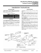
These instructions cover the installation of the Non-Electrical
Subbase Accessory. The Non-electrical Subbase Accessory
package consists of the subbase, 2 adjustable side extension pan-
els, and 4 attachment screws. See Fig. 1.
PACKAGE CONTENTS
ITEM
QUANTITY
Non-Electrical Subbase
1
Adjustable Side Extension Panels
2
Attachment Screws (black)
4
GENERAL
The non-electrical accessory subbase must be used whenev-
er the packaged terminal air conditioner (PTAC) or heat
pump is installed in a wall less than 2 in. thick, or where wall
sleeve extends 4 in. or more into room, or for additional
support or leveling of air conditioner or heat pump. Wall
sleeve must be 3
1
/
4
in. minimum into room and 3
1
/
4
in.
minimum to 5
1
/
2
in. maximum above floor.
NOTE: If electrical connections are required, either an electri-
cal subbase or electrical accessory kit can be ordered from the
factory.
INSTALLATION
To properly install the subbase, follow these simple
instructions:
Step 1 —
Prepare wall sleeve. Drill one
1
/
8
in. hole on each
side of wall sleeve. If installing plastic sleeve, use locator dim-
ple on outside of sleeve, found near bottom, front section.
Drilling can be done through the plastic from inside if desired.
See Fig. 1.
NOTE: If installing metal sleeve, mark location of holes on
sleeve then drill
1
/
8
-in. holes. See Fig. 2 for locator hole dimen-
sions on metal sleeve.
Step 2 (Optional) —
Adjustable Side Extension Panels
can be attached to cover open space left between subbase and
wall. Determine the distance from inside wall to front of wall
sleeve. See Fig. 3, dimension X.
Step 3 —
Attach Side Extension Panels to subbase using
1 black screw on each side so that panel end extends dimension
X plus 2 in. from front of subbase. To adjust side panel, simply
bend panel at slot position. See Fig. 1.
Step 4 —
Attach subbase to wall sleeve. Subbase has side
tabs for mounting the subbase to the sleeve. Be sure hole on
side tab is lined up with locator hole on side of sleeve. Once
holes are aligned, attach subbase to sleeve with (1) one black
screw on each side. Do not overtighten. See Fig. 1 and 3.
Step 5 —
Level subbase flush with floor by adjusting level-
ing bolts beneath each end of subbase. See Fig. 4 for completed
subbase assembly.
PC 132 Catalog No. 535-20020 Printed in U.S.A. Form 52C,P-1SI Pg 1 5-01 Replaces: 52S-
Manufacturer reserves the right to discontinue, or change at any time, specifications or designs without notice and without incurring obligations.