USER GUIDE UB - E920 Wheelchair Accessible
Introduction Training with the E920 Congratulations on your purchase of E920. FIRST DEGREE FITNESS is proud to present the Rower as a FULL COMMERCIAL USE product featuring patented Adjustable Fluid Resistance. As with any piece of fitness equipment, consult a physician before beginning your E920 exercise program. Follow all instructions carefully for correct assembly, tank filling, water treatment, service and safety. Access to our world-wide distributor and service network is available at www.
Contents Safety ................................................................................... 4 Assembly - UB-E920 ............................................................... 6 UB-920 Box 1 & 2 Contents .................................................... 7 Assembly Instructions ............................................................. 8 Operation Instructions ............................................................... 13 Maintenance ........................................................
Safety Safety Information • Before using this product, it is essential to read this ENTIRE operation manual and ALL instructions. The Rower is intended for use solely in the manner described in this manual. • UNDERSTANDING EACH AND EVERY WARNING TO THE FULLEST IS IMPORTANT • As with any piece of fitness equipment, consult a physician before beginning your Rower exercise program.
Safety Proper Usage • Do not use any equipment in any way other than designed or intended by the manufacturer. It is imperative that FIRST DEGREE FITNESS equipment is used properly to avoid injury. • Injuries may result if exercising improperly or excessively. It is recommended that all individuals consult a physician prior to commencing an exercise program. If at any time during exercise you feel faint, dizzy or experience pain, STOP EXERCISING and consult your physician.
Assembly - UB-E920 Product Specifications Product Class: SC Braking System: Speed Independent Product Net Weight: 90kg (198lb) Product Gross Weight: 110kg (242lb) Maximum Safe Operating Surface Area: 301cm (108.27”) Length x 222cm (87.40”) Width Dimensions: 1810mm (71.26”) Length x 1020mm (40.16”) Width x 148mm (58.
UB-E920 Box 1 & 2 Contents Item Qty. Description Item Qty.
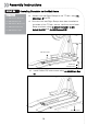
Assembly Instructions STEP 1 Mainframe Assembly Instructions REQUIRED 4 x M8 x 15mm Blots [7] 1 a) Attach Telescoping Tube to the underside of the control arm using 4x M8x15mm Bolts[7] and 4x M8 Spring Washers[17]. b) Thread the 3x Foot levelers[18] into underside of base. Adjust as required. 4 x M8 Spring Washers [17] 2 3 x Foot Levelers [18] 12 CAUTION 8 The control arm is heavy and may swing freely during this stage of assembly.
Assembly Instructions STEP 3a Installing Baseplate to the Mainframe REQUIRED 1 T-Track Ramp Right T-Track 2 Ramp Left 2 x PVC12 Side Covers 3 x M10x20mm Blots [11] 8 2 x M10 Nylock Nut [13] PVC Side Covers Ramp Right 3 x M10 Washer [16] Ramp Left Remove contents from box and make sure all parts are present. Contents will include the T-track, left/right side ramps and bolt pack (note, this may also be located with Seat Assembly).
Assembly Instructions STEP 3b Installing Baseplate to the Mainframe REQUIRED 4 x M8 1 x20mm b) Attach Left and Right Ramps to the T-Track using 8x M8x45mm Bolts[10]. c) Once the Left and Right Ramps have been installed to the sides of the T-Track, secure the front end of each Ramp as shown using 4x M8x25 Bolts[9], 4x M8 Nylock Nut[12] and 4x M8 Washers[15].
Assembly Instructions STEP 4 Installing Seat Assembly REQUIRED a) Thread the Handle Bar[19] through the Shaft Seat Frame1 [3] b) Tighten the Handle Bar[19] with the M10 Dome Nut[13]. Seat Back [4] c) Install Seat Back[4] with 4x M6x20 Bolts[6] and M6 Washer[14]. d) Install Lower Seat[5] with 4x M6x20 Bolts[6] and M6 Washer[14].
Assembly Instructions STEP 5 Installing Seat to the Mainframe CAUTION a) Seat Stop: Must be lowered to allow seat onto Baseplate track. Must ALWAYS be in the LOCKED position when seat is occupied on Baseplate. Must be lowered to allow seat removal. To LOCK, raise and locate. To UNLOCK, lift and drop rearward. b) Seat Installation: Tilt the seat slightly upward to allow the front rollers to engage the channel.
Operation Instructions E920 Control Arm Chain Tensioning Bolts: Allows for tightening the chain or adjustment from side to side. Make sure when tightening only to adjust the same amount for both bolts, otherwise the sprocket will be misaligned. Note: Tightening the right bolt only (turning clockwise) will pull the right side of the crank assembly toward you, tightening the left will pull the left side toward you.
Operation Instructions Slider Arm Kit Installation Instructions a) Mount the left Slider Arm onto the Axle using the yellow indicator hole to align the slider and axle. b) Tighten the set screw onto the Axle and into the yellow indicator hole using the 3mm Allen key. c) d) Thread Adjustment Knob onto the Axle to secure the assembly. Repeat steps 1-3 to install right Slider Arm onto the Axle.
Operation Instructions Additional Exercises Training can now be achieved with both left and right Handgrips moving parallel , rather than in an opposed motion. a) On the right Slider Arm Assembly, remove the Adjustment Knob, loosen set screw and remove Assembly from the Axle. b) As shown below, rotate right Slider Arm 180 degrees and reinstall onto the Axle. There is an additional screw locator hole located on opposite side of axle .
Operation Instructions Tank Filling and Water Treatment REQUIRED Funnel and Hose [20] CAUTION Use a drop cloth under the tank when filling to avoid damage floor or carpet. Do not fill past the calibration mark as indicated on the tank level sticker or water spillage may occur. WARNING a) b) Filling requires a large bucket (not Supplied) and the supplied water Funnel and Hose[20]. Filling will take approximately 8 liters of water.
Operation Instructions Integrated Performance Monitor [IPM] Operation Quick start: Provides instant workout information. Just start training to activate. You can choose to change UNITS displayed UNITS: Displays WATTS, SPM, HR, 500/m LEVEL: Adjustable from 1-20. Match LEVEL number with resistance level on the Fluid tank.
Maintenance All preventive maintenance activities must be performed on a regular basis. Performing routine preventive maintenance actions can aid in providing safe, trouble-free operation of all First degree fitness equipment. First degree fitness is not responsible for performing regular inspection and maintenance actions for your machines. Instruct all personnel in equipment inspection and maintenance actions and also in accident reporting and recording.
Troubleshooting Fault Probable Cause Solution Water changes color or becomes cloudy. Rower is in direct sunlight or has not had water treatment. Change rower location to reduce direct exposure to sunlight. Add water treatment or change tank water as directed in the water treatment section of this manual. Consider using distilled water to refill tank. Knocking noise from inside the control arm while training, especially when changing directions. Chain requires tightening or adjustment.
Tank Belt Adjustment 1. Remove large metal inspection plate. 2. Using a long tool, push out the rear end cap as pictured below left. This will give you access to the tank End Cap 4. Using a 6mm Allen Key, tighten the Belt using the Tank Tensioning Bolt until the belt no longer slips during hard rowing. 3. Loosen both the rear and front tank bolts slightly as shown. Remove front Rubber Belt Cover. Tank Tensioning Bolt Note: Do not over tighten tank bolts.
International Warranty FULL COMMERCIAL USE This product is designed and constructed for use in any Health Club / Fitness Studio application First Degree Fitness Limited warrants that the Upper Body Ergometer (model UB-E920), purchased from an authorized agent and in its undamaged original packaging, is free from defects in materials and workmanship.
CONTACT US For customer support please visit firstdegreefitness.com/support TAIWAN T: +886 3 478 3306 764 Chung Shan South Rd Yangmei Taoyuan Taiwan R.O.C.