
Instruction Manual


33
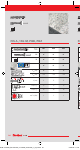
Table III Processing and curing times
Temperature range Working time/
processing time
Curing time
°C °F
– 5 to ± 0 +23 to + 32 – 24 h
> ± 0 to + 5 > +32 to + 41 13 min 180 min
> + 5 to +10 > +41 to + 50 9 min 90 min
> +10 to +20 > +50 to + 68 5 min 60 min
> +20 to +30 > +68 to + 86 4 min 45 min
> +30 to +40 > +86 to +104 2 min 36 min
Storage temperature: + 5 °C – + 25 °C / + 41 °F – + 77 °F
+41°F – +77°F
+5°C – +25 °C
Store mortar
in a cool dry place
fischer Injection Mortar FIS V Plus
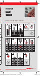
A Preparing the cartridge
1. Remove the cap by turning it to left and pulling it off.
2. Insert the static mixer and lock it in place (turn to the right). The spiral mixer in the static mixer must
be clearly visible. Never use without the static mixer !
3. Place the cartridge in the dispenser.
4. Press approx 10 cm of material out until the resin mortar comes out evenly grey in colour. Mortar
which is not grey colour will not cure and must be disposed of.
5. The temperature of the concrete must be at least 23°F (5°C) and at most 104°F (40°C) (see Table III).
The temperature of the cartridge must be at least ϑ=41°F (5°C).
6. After finishing work, leave the static mixer attached to the cartridge.
Important: If the processing time is exceeded, use a new static mixer and if necessary remove encrusted
material in the cartridge mouth.
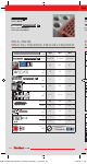
B Installation
Important: Installation instructions – follow the pictograms 1–7 for the se quence of operating and refer to
Tables I–III for setting details. The construction draw ings must be adhered. For any applications not covered by
this document or by any problems with installation contact fischer.
1. Drill hole with a hammer drill set. Observe the correct hole diameter and depth according to Table I and
Table II.
2.1/2.2/2.3. Standing water in bore holes must be completely removed by blowing out before cleaning the bore
hole. The drill hole must blown out four times with compressed air (oil-free ≥ 87 psi (6 bar)), brushed
four times (minimal by hand) starting from the bottom of the hole and then again blown out four times with
com pressed air (oil-free ≥ 87 psi (6 bar)). For drill holes d
o
< 18 mm it is allowed to use hand pump. The
dia meters of the brushes are given in Table I. Clean dirty brushes. Check brushes for wear with brush gauge
(brush Ø ≥ drill hole Ø). If required use brush extension.
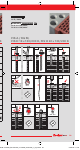
3. Fill approx. ⅔ of the hole with mortar starting from the bottom of the hole. For drill hole depth > 150 mm use
an extension tube. Observe processing time.
4. Anchoring element must be straight and free of oil and other contaminants. Mark the anchor with correct
embedment depth. Press the anchoring element down to the bottom of the hole, turning it slightly while so
doing. After insert the anchoring element, excess mortar must emerge from the mouth of the hole.
5. For overhead installations and applications between horizontal and overhead use the appropriate injection
adapter and wedges to support the anchor during curing time. Also use an injection adapter for all applications
with a drill hole depth > 250 mm or a drill hole diameter d
o
≥ 30 mm. Use appropriate accessories to capture
excess adhesive during installation of the anchor element in order to protect the unbonded portion of the
anchor element from adhesive.
6. Do not disturb the anchoring element until cure time has elapsed. Do not apply load or installation torque
moment to the anchor until the prescribed curing times are elapsed. The allowable working time and the
minimum curing time are given in Table III.
7. The installation torque moments are given in Table II.
PBZ
Installation instruction
see ICC-ES Evaluation Report No. 2786
at www.icc-es.org
MOAL-100x200_FIS-V-PLUS_nonverbal_00181240_(1)_ajm.indd 33MOAL-100x200_FIS-V-PLUS_nonverbal_00181240_(1)_ajm.indd 33 24.08.22 11:2424.08.22 11:24