DOUBLE DISHDRAWER TM DISHWASHER DD24DA & DD24DCT models INSTALLATION GUIDE US CA 591153B 08.
1 ! SAFETY AND WARNINGS IMPORTANT SAFETY INSTRUCTIONS WARNING! Electrical Shock Hazard Before installing the dishwasher, remove the house fuse or open the circuit breaker. If permanently connecting the dishwasher, be sure the power is isolated and the dishwasher unplugged. ● ● ● ● GROUNDING INSTRUCTIONS This appliance must be grounded. In the event of a malfunction or breakdown, grounding will reduce the risk of electric shock by providing a path of least resistance for electric current.
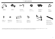
2 Drain hose support (1) Phillips 5⁄8” (16 mm) screws (9) Drain hose joiner (1) Rubber washer for inlet hose (1) (comes already fitted) Wire clip (2) (for securing Drain hose joiner) Moisture protection tape (1) (to prevent moisture damage to cabinetry) PARTS SUPPLIED Clamp (1) (for securing Drain hose joiner) Hexagonal socket for feet adjustment (2) (long & short) Side mounting bracket kit (A and B) (2) OPTIONAL Prefinished toekick (1) Top mounting brackets (2) OPTIONAL Edge Protector (1) (If
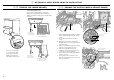
3 3-A OPTIONALLY HARD WIRING PRIOR TO INSTALLATION 3-B REMOVE THE LOWER DRAWER REMOVE THE ACCESS COVER & REMOVE POWER To prevent kinked hoses Either sit the drawer down on the left hand side (recommended) or rotate the drawer clockwise, resting it on its side after removal. 3 3 1 Clip 1 1 Access cover 4 Push drawer runners back in on either side. 1 Sit the drawer down 2 00 4” (1 2 mm) 3 3 4 5 Press the release tabs in on either side and push back to release drawer from runners.
3 3-C OPTIONALLY HARD WIRING PRIOR TO INSTALLATION TERMINATE MAINS WIRING AS SHOWN AND REPLACE MODULE AND COVERS 8 12 8 9 10 9 11 12 14 13 13 11 14 IMPORTANT! Ensure the mains wires are routed UNDERNEATH all other harness wiring from the electronics module. 10 3-D REFIT THE DRAWER ONTO THE RUNNERS & CLOSE 2 Lift or rotate counter-clockwise the drawer back onto the drawer runners on either side.
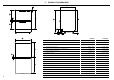
4 PRODUCT DIMENSIONS C J H K G F A I L FRONT M PROFILE N B PRODUCT DIMENSIONS D E O PLAN 5 DD24DA DD24DCT INCHES (MM) INCHES (MM) 32 5/16 - 34 5/8” (820-880)2 34 - 36 3/8” (864-924)2 A Overall height of product1 B Overall width of product 23 9/16” (599) 23 9/16” (599) C Overall depth of product 22 9/16” (573) 22 9/16” (573) D Depth of chassis (to back of front drawer panel) 21 3/4” (553) 21 3/4” (553) E Depth of drawer front panel 13/16” (20) 13/16” (20) F Height of
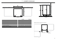
5 CABINETRY DIMENSIONS Q S P R T Bracket slots PLAN CABINETRY DIMENSIONS PROFILE DD24DA DD24DCT INCHES (MM) INCHES (MM) P Inside height of cavity* min. 32 5/16” (820) min. 34” (864) Q Inside width of cavity 23 5/8” (600) 23 5/8” (600) R Inside depth of cavity min. 22 1/16” (560) min.
6 CAVITY PREPARATION IMPORTANT! COUNTERTOP 3/8” (10 mm) Moisture protection tape must be applied. The power outlet must be located in a cabinet adjacent to the dishwasher cavity. 110-120 VAC max. 15 A Water Connection Recommended HOT (Maximum 140°F/60°C). Supplied hose to suit 3⁄8” (9 mm) male compression fitting. Water Pressure These marks indicate formed bracket screw locations, if securing by drawer removal. Water softener models Max. 1 MPa (145 psi) Min. 0.1 MPa (14.
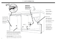
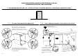
7 MAXIMUM DISTANCE OF HOSES & CORD FROM CHASSIS EDGE LEFT HAND SIDE Drain hoses - 78 1/2” (2000 mm) Inlet hose - 64 3/4” (1650 mm) Power cord (excl.plug) - 29 1/2” (750 mm) RIGHT HAND SIDE Drain hoses - 70 1/2” (1800 mm) Inlet hose - 49” (1250 mm) Power cord (excl.
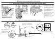
NOW CHOOSE WHICH INSTALLATION METHOD (A) OR (B) IS MORE SUITABLE FOR YOUR CABINETRY... 8 RECOMMENDED METHOD (A) - SECURE WITHOUT DRAWER REMOVAL (FRAMELESS CABINETRY ONLY) 9-A B ATTACH SIDE MOUNTING BRACKETS Clip all four side mounting brackets into their slots using a flat-bladed screwdriver. Ensure they’re securely fitted before sliding product into cavity.
!1-A SECURE TO THE CABINETRY ON THE SIDES !2-A OPTIONALLY SECURE TO THE CABINETRY ABOVE 1 Open the drawer halfway. Using a flat bladed screwdriver, prise the gray rubber plug out of the trim moulding. (x2) The top mounting brackets will only bend upwards a maximum of 3/8” (10 mm). Replace the gray rubber plug back into the trim moulding and ensure the trim seal is facing forward.
8 9-B (x2) ALTERNATIVE METHOD (B) - SECURE BY DRAWER REMOVAL !0-B PULL THROUGH HOSES & PUSH INTO THE CAVITY REMOVE THE LOWER DRAWER To prevent kinked hoses Either sit the drawer down on the left hand side (recommended) or rotate the drawer clockwise, resting it on its side after removal. optionally attach the two top mounting brackets 3 Initially level the product 1 4 Sit the drawer down 2 You can raise or lower the product by twisting the feet.
!1-B !2-B SECURE TO THE CABINETRY ON THE SIDES OPTIONALLY SECURE TO THE CABINETRY ABOVE (x2) For further adjustment, using the most appropriate length Hexagonal socket supplied, fully extend leveling feet up to required distance by hand. The top mounting brackets will only bend upwards a maximum of 3/8” (10 mm). Secure using two pairs of formed brackets (use 5⁄8” (16 mm) screws). Repeat on the other side of the chassis. x4 Hexagonal socket Ensure product is level and aligning with cabinetry.
!4-B Where the toekick meets the bottom of the tub is the cut-off point 3 5 Lay the toekick face down on a chopping board or similiar 4 Turn the toekick over and score along the same line 6 Smooth the edges with a file. Be careful of sharp edges.
!5 THERE ARE THREE DIFFERENT PLUMBING AND DRAINAGE OPTIONS. CHOOSE WHICH IS MORE SUITABLE. DRAINAGE OPTION 1 Dishwasher and Ø 1 1/2” (38 mm) Standpipe If space is limited for fixing, push hose through drain hose support to required height 2 29 1/2”-34 3/4” (750-882.5 mm) Screw Drain hose support to back wall at correct height max. 4 3/4 po (120 mm) step 16 IMPORTANT! min.
DRAINAGE OPTION 2 Dishwasher using Dual Air Gap/Break with Drain Hose Joiner IMPORTANT! We recommend the use of a commercially available Dual (Double) Air Gap/Break Kit. This provides totally separate draining for each drawer and eliminates possible “cross draining” problems Drain hose Drain hose 2 Secure both drain hoses to a Dual Air Gap/Break 1 37 3/8” (950 mm) Max. height to top of Air Break (countertop or wall mounted) step 16 min.
DRAINAGE OPTION 3 Dishwasher using drain hose joiner onto sink trap/waste tee Screw Drain hose support to back wall at correct height 2 29 1/2”-34 3/4” (750-882.5 mm) If space is limited for fixing, push hose through drain hose support to required height Supplied drain hose joiner to suit Ø 3/4” (19 mm) waste tee max. 4 3/4 po (120 mm) 3 min. R 8” (200 mm) IMPORTANT! Ensure that drain connection will comply with local plumbing regulations. 29 1/2 - 34 3/4” (750-883 mm) step 16 min.
!6 !7 CONNECT INLET HOSE TO HOT WATER SWITCH PRODUCT ON 180o No leaks! Ensure the supplied rubber washer is fitted inside the coupling. Tighten coupling with spanner. 1 2 !8 ● ● TROUBLESHOOTING Excessive water remaining above the filter plate, after the rinse cycle. (This is displayed as an A3 fault) Check for a kinked drain hose, blocked waste connection, highloop not properly installed, drain hose not routed correctly or spray arms not in place. No water supply.
!9 FINAL CHECKLIST TO BE COMPLETED BY THE INSTALLER Check all parts are installed. Ensure that all panels and parts thereof are secure and final electrical tests have been conducted in accordance with local electrical regulations. Turn on the power and water supplies, then open the drawers. You should hear a beep and see a program indicator light up on the internal control panel. Check the spray arms are in place, mounted correctly and free to rotate, by physically rotating by hand.