INSTALLATION INSTRUCTIONS Gas-on-glass cooktop CG302D, CG451D, CG603D, CG604D, CG752D, CG903D & CG905D models NZ AU 590149D 02.
1 SAFETY AND WARNINGS WARNING! Electrical shock hazard Before carrying out any work on the electrical section of the appliance, it must be disconnected from the mains electricity supply. Connection to a good earth wiring system is absolutely essential and mandatory. Alterations to the domestic wiring system must only be made by a qualified electrician. Failure to follow this advice may result in electrical shock or death. WARNING! Cut hazard Take care - some panel edges are sharp.
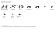
2 PARTS SUPPLIED Dual Wok Pan support (Models with a Dual Wok only) Clamping brackets (4) and screws (4) Pan support (not supplied with Dual Wok only models) LPG test point adaptor (1) (LPG models only) Mini wok Pan support (1) (CG604D only) Small pan support (1) (some models only) Wok stand (1) NG regulator (1) (NG models only) Installing multiple products Note: if installing multiple products adjacent to each other within the same cutout, a separate joining strip kit is required for installati
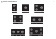
3 GAS RATE SUMMARY-MODELS 4 SEMI-RAPID SEMI-RAPID DUAL WOK DUAL WOK SEMI-RAPID AUX CG302D SEMI-RAPID CG451D CG603D SEMI-RAPID DUAL WOK MINI WOK DUAL WOK AUX CG604D CG752D SEMI-RAPID SEMI-RAPID DUAL WOK DUAL WOK SEMI-RAPID DUAL WOK RAPID CG903D CG905D AUX
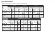
3 GAS RATE SUMMARY 5 All appliances are factory set for Natural gas or LPG and are not convertible. Check the appliance data label. CG302D BURNER AUX CG451D SEMI-RAPID CG603D DUAL WOK SEMI-RAPID DUAL WOK Jet size (mm) Nominal rating (MJ/h) Jet size (mm) Nominal rating (MJ/h) Jet size (mm) Nominal rating (MJ/h) Jet size (mm) Nominal rating (MJ/h) Jet size (mm) Nominal rating (MJ/h) NG (1.00 kPa)* 1.00 5.0 1.35 8.8 1.43 1.43 0.70 21.0 1.30 8.4 1.26 1.26 0.70 16.6 LPG (2.
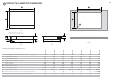
4 PRODUCT & CABINETRY DIMENSIONS 6 G B C H I TOP TOP Note: Gas inlet connection is located in the rear right corner.
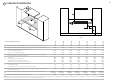
5 CLEARANCE DIMENSIONS 7 I E D C F A G B H ISO FRONT CG302D CG451D CG603D CG604D CG752D CG903D CG905D minimum clearance from left edge of cutout to nearest combustible surface 120 60 115 130 115 115 130 minimum clearance from right edge of cutout to nearest combustible surface minimum clearance from rear edge of cutout to: nearest combustible surface nearest non-combustible surface minimum height of non-combustible material when used on adjacent walls minimum clearance from glass sur
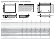
6 FLUSH MOUNTING INSTALLATION (NOT RECOMMENDED) B 8 G G WARNING! We do not recommend flush mounting and sealing as servicing requires the cooktop to be removed from the benchtop. The owner carries all risk for flush mounting the cooktop. The owner must ensure the cooktop has been cut out from the benchtop before servicing can be carried out.
6 FLUSH MOUNTING INSTALLATION 6a ROUTER THE BENCHTOP TO THE SPECIFIED DEPTH (NOT RECOMMENDED) 6b FIT THE CLAMPING BRACKETS 9 6c MASK OFF THE AREA TO BE SILICONED x4 1 view from below 2 3 Choose most appropriate slot for benchtop 5 mm 16 - 50mm 6d APPLY SILICONE 6e WIPE OFF EXCESS SILICONE 6f IF REMOVING PRODUCT, CUT AROUND THE SILICONE TO REMOVE PRODUCT 2 min. 150 OC rated 1 Ensure silicone does not leak underneath glass.
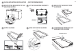
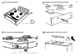
7 DISCARD PACKAGING 8 REMOVE THE TWO TRANSIT SCREWS Recycle responsibly 9 FIT THE ELBOW AND WASHER Fibre washer Floating nut Repeat on the other side 10 LOWER GENTLY INTO THE CUTOUT Elbow (1/2” BSP external thread) 10
FIT CLAMPING BRACKETS BASED ON THE 11 12 SECURE TO BENCHTOP BENCHTOP THICKNESS x4 view from below x4 16-20mm 20-30mm 30-40mm 40mm+ 13 CONNECT TO GAS SUPPLY NG Models Arrow Make sure to fit the supplied regulator. Adjust to obtain a test point pressure of 1 kPa with all burners operating at highest setting. LPG Models Repeat on all the other sides 14 CHECK ALL CONNECTIONS FOR GAS LEAKS Make sure to fit the supplied test point adaptor. Make sure the supply pressure is regulated to 2.
15 AFFIX DUPLICATE DATA LABEL SOMEWHERE ACCESSIBLE & PLUG COOKTOP IN 16 FIT PAN SUPPORTS Ensure the pan supports are located securely and in the correct orientation (refer to User guide) Duplicate data label 17 TEST OPERATION To check that the ignition system operates correctly, light each burner by itself, then all burners in combination. Check for a well‐defined blue flame without any yellow tipping.
18 FINAL CHECKLIST 13 TO BE COMPLETED BY THE INSTALLER Installer’s name: Have you installed the clamping brackets? Installer’s signature: Have you verified that the type of model (factory-set for NG or LPG) matches the type of gas at the site of installation? Installation company: Date of installation: Have you used the fibre washer supplied? Have you leak-tested all connections? LEAVE THESE INSTRUCTIONS WITH THE CUSTOMER Is the appliance set to the correct working pressure? Have you affixed the sup