
Installation Instructions


11
11
13
12
14
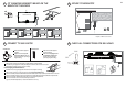
FIT CLAMPING BRACKETS BASED ON THE
BENCHTOP THICKNESS
CONNECT TO GAS SUPPLY
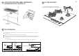
SECURE TO BENCHTOP
CHECK ALL CONNECTIONS FOR GAS LEAKS
16-20mm
20-30mm
x 4
30-40mm
40mm+
view from below
x 4
Repeat on all the other sides
GAS
ON
GAS
ON
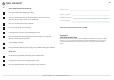
NG Models
ALL Models
Make sure the connection point will be accessible with the cooktop installed.
To enable the gas supply to be readily shut o by the customer, make sure the connection
is tted with an isolating valve close to the cooktop.
Make sure to t the supplied
regulator.
Adjust to obtain a test point
pressure of 1 kPa with the two
semi-rapid burners operating at
highest setting.
Ensure the hose is long enough to allow for removal of cooktop for servicing.
Make sure the connector is located as shown in step 5 CLEARANCE DIMENSIONS.
The hose assembly must be AS/NZS 1869 Class B or D certied, with an Rp ½” (ISO 7‐1) female thread connection.
The hose assembly must be as short as practicable and comply with relevant AS 5601/NZS 5261 requirements.
The hose must not be kinked, subjected to abrasion or permanently deformed.
The hose must not be near or in contact with any hot surfaces
(e.g. base of metal hotlplate, ue, or chassis of underbench oven etc.)
If connecting the gas with a exible hose:
LPG Models
Make sure to t the supplied
test point adaptor.
Make sure the supply pressure
is regulated to 2.75 kPa, with
the two semi-rapid burners
operating at highest setting.
Arrow