INSTALLATION INSTRUCTIONS Induction cooktop CI302DTB3 CI603DTB2, CI604DTB3, CI754DTB2, CI905DTB2 & CI905DTB3 models NZ AU GB IE SG www.fisherpaykel.com 590492E 02.
1 ! SAFETY AND WARNINGS IMPORTANT SAFETY INSTRUCTIONS WARNING! Electrical shock hazard Disconnect the appliance from the mains electricity supply before carrying out any work or maintenance on it. Connection to a good earth wiring system is essential and mandatory. Alterations to the domestic wiring system must only be made by a qualified electrician. Failure to follow this advice may result in electrical shock or death. ● ● ● ● ● ! WARNING! ● Cut Hazard Take care - panel edges are sharp.
1 SAFETY AND WARNINGS IMPORTANT SAFETY INSTRUCTIONS ● ● ● ● ● ● ● ● 2 Before you install the appliance, please make sure that a suitable disconnection switch is incorporated in the permanent wiring, mounted and positioned to comply with the local wiring rules and regulations. A means of disconnection with at least a 3 mm air gap contact separation in all poles must be incorporated into the fixed wiring in accordance with the wiring rules, unless the local wiring rules allow for alternative means.
2 Clamping brackets (4) and screws (4) PARTS SUPPLIED Foam tape (1) CI302DTB2 only Clamping brackets (2) and screws (2) Installing multiple products ● ● ● ● Note: We recommend installing products in separate cutouts with a minimum distance of 5 mm between the glass edges. If installing multiple products adjacent to each other within the same cutout, a separate joining strip kit is required for installation.
3 PRODUCT & CABINETRY DIMENSIONS G B Note: Electrical connection is made at the right rear C H I TOP TOP A E D REAR SIDE CI302DTB CI603DTB CI604DTB CI754DTB CI905DTB mm mm mm mm mm 54 54 54 54 54 B Overall width of product 300 600 600 750 900 C Overall depth of product 530 530 530 530 530 49 49 49 49 49 E Width of chassis 257 549 549 719 855 F Depth of chassis 478 478 478 478 482 G Overall width of cutout 265 560 560 725 870 PRODUCT AND CABINETRY
4 CLEARANCE DIMENSIONS min. 4 mm min. 75 mm B Drawer or other obstruction Alternatively 2x 50mm holes in side wall to allow adequate cool air D A E C Alternatively 2x 50mm holes in side wall to allow adequate cool air E C min. 4 mm Oven with cooling fan ISO 20 mm ! FRONT Ventilation gap must be present WARNING! This cooktop requires adequate supply of cool air to fully function. The base of the cooktop must have direct unrestricted ventilation to the room where the cooktop is installed.
5 FLUSH MOUNTING INSTALLATION (NOT RECOMMENDED) B Note: Electrical connection is made at the right rear C ! G G WARNING! We do not recommend flush mounting and sealing as servicing requires the cooktop to be removed from the benchtop. The owner carries all risk for flush mounting the cooktop. The owner must ensure the cooktop has been cut out from the benchtop before servicing can be carried out.
5 A FLUSH MOUNTING INSTALLATION ROUTER THE BENCHTOP TO THE SPECIFIED DEPTH B (NOT RECOMMENDED) FIT THE CLAMPING BRACKETS C MASK OFF THE AREA TO BE SILICONED 1 No. of brackets and slot positions depends on model view from below 2 3 12-40mm 5 mm 40mm+ Fit a minimum of 2 brackets on opposing sides D APPLY SILICONE E F WIPE OFF EXCESS SILICONE IF REMOVING PRODUCT, CUT AROUND THE SILICONE TO REMOVE PRODUCT 2 min. 150 OC rated 1 Ensure silicone does not leak underneath glass.
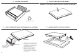
6 DISCARD PACKAGING 7 PLACE COOKTOP UPSIDE DOWN IMPORTANT! - To avoid damage to the glass, ensure there is a protective cover underneath it. Recycle responsibly 8 APPLY ADHESIVE FOAM TAPE AROUND GLASS EDGE Foam Tape Adhesive side Ensure edge of tape lines up with outer edge of cooktop 8 1 Apply the foam seal around the glass overhang, 5 mm in from the edge of the glass, with the adhesive side facing down to form a continuous seal around the cooktop.
!0 CONNECTING THE COOKTOP TO THE MAINS POWER SUPPLY IMPORTANT! ● ● ● ● ● ● Connection diagrams This cooktop must be connected to the mains power supply only by a suitably qualified person. To connect the cooktop to the mains power supply, do not use adapters, reducers, or branching devices, as they can cause overheating and fire. The power supply cable must not touch any hot parts and must be positioned so that its temperature will not exceed 75 oC at any point.
!1 FINAL CHECKLIST TO BE COMPLETED BY THE INSTALLER Is the cooktop earthed? Check that there is an adequate and constant flow of cool air from the cabinetry to the base of the cooktop. Check that the power supply cable is not accessible via cupboard doors or drawers and that it is NOT touching the cooktop. Is the cooktop clamped down securely? Check that the pan detection feature is working correctly. Turn on each cooking zone without putting any cookware on them.
11
www.fisherpaykel.com Copyright © Fisher & Paykel Appliances 2017. All rights reserved. The product specifications in this booklet apply to the specific products and models described at the date of issue. Under our policy of continuous product improvement, these specifications may change at any time. You should therefore check with your Dealer to ensure this booklet correctly describes the product currently available. NZ AU GB IE SG 590492 E 02.