Installation Instructions NZ & AU CG603 SERIES CG903 SERIES CG913 SERIES 599284 B 07.
Safety & Warnings WARNING Cut Hazard Beware of sharp edges when handling stainless steel appliances. Failure to use caution could result in injury or cuts. WARNINGS! Particular attention shall be given to the relevant requirements regarding ventilation. This product should not be sealed into the bench with silicone or glue. Doing so will make future servicing difficult.
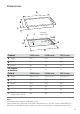
Dimensions A B C J F manifold centre line H gas inlet E G D Product A Width B Depth C Height Pan support to Benchtop Cutout D Width E Depth F Radius G H J Clearance to nearest combustible surface CG603 series CG903 series CG913 series 578 914 914 511 533 546 40 40 76 43 43 22 CG603 series CG903 series CG913 series 560 (558-562) 870 (846-882) 870 (860-882) 490 (485-495) 494 (478-501) 494 (486-524) R10 R10 R10 30 30 30 40 47 35 60 60 81 Note: All measurements give
Clearances a b d e g f c a 600 mm minimum from top of trivet to rangehood. 750 mm minimum from top of trivet to overhead exhaust fan. (Fisher & Paykel splashbacks are 750 mm high). b 600 mm minimum from top of trivet to downward facing combustable surface. (450 mm minimum if protected by tiles or fire resistant materials).
Installation Instructions Standards Requirements Gas Supply Connection Australian and New Zealand Gas Installation Standards (AS5601, NZS 5261) require a cooktop to be installed so that the surface temperature of any nearby combustible surface will not exceed 65oC above ambient. This cooktop is supplied set up for Natural Gas but is suitable for installation with either Natural Gas or LPG. Refer to relevant table for pressures and appropriate orifice sizes.
Installation Instructions Natural Gas For Natural Gas usage the gas supply is connected to the regulator which is supplied loose with a built in test point - 1kPa (4” WG) and the inlet connection of 1/2 “ B.S.P. (male thread). Do not over tighten. The operation of the appliance, including the ignition system, must be tested before installation is complete.
Installation Instructions 12 Turn on main electrical supply and light the Minimum Setting or Turn Down burners. 13 Important! This has been set at the factory for NG but may need adjusting for local conditions. 14 Check all burners have good flame (see When converting to LPG, the minimum setting MUST be reset for each burner. Reset the minimum setting (see ‘Minimum Setting or Turndown’). fig.3,4,5). To adjust the minimum setting you will need a Ø 2.5 x 45 mm screwdriver.
Installation Instructions Gas Rate Summary Burners Natural Gas Orifice size MJ/h@1 kPa LPG Orifice size MJ/h@2.75 kPa CG603 Auxiliary Burner (RH front) 0.85 mm 3.6 MJ/h 0.55 mm 4.0 MJ/h Semi-Rapid Burner (LH & RH rear) 1.3 mm 8.5 MJ/h 0.8 mm 8.5 MJ/h Wok Burner (LF front) 1.75 mm 15 MJ/h 1.00 mm 13.5 MJ/h Rapid Burner (LH front) 1.55 mm 12 MJ/h 0.95 mm 12 MJ/h Auxiliary Burner (RH front) 0.85 mm 3.6 MJ/h 0.55 mm 4.0 MJ/h Semi-Rapid Burner (LH & RH rear) 1.3 mm 8.5 MJ/h 0.