INSTALLATION INSTRUCTIONS DishDrawerTM dishwasher DD24S 7 & DD24ST 7 models US CA 590204D 04.
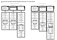
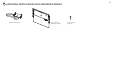
1 FOLLOW THE INSTALLATION SEQUENCE RELEVANT TO YOUR MODEL TALL HEIGHT SINGLE MODELS STANDARD HEIGHT SINGLE MODELS Classic Designer Integrated DD24SCX7 DD24SCW7 DD24SCB7 DD24SDFX7 DD24SI7 PARTS SUPPLIED PARTS SUPPLIED PRODUCT & CABINETRY DIMENSIONS (STANDARD HEIGHT) PRODUCT & CABINETRY DIMENSIONS (STANDARD HEIGHT) PARTS SUPPLIED + EXTERNAL VENTING KIT OPTIONALLY HARD WIRING OPTIONALLY HARD WIRING CAVITY PREPARATION CAVITY PREPARATION MAXIMUM DISTANCE OF HOSES & CORD FROM CHASSIS EDGE MAXIMUM
2a SAFETY AND WARNINGS - ALL MODELS WARNING! Electrical hazard Before installing the dishwasher, remove the house fuse or open the circuit breaker. If permanently connecting the dishwasher, be sure the power is isolated and the dishwasher unplugged. GROUNDING INSTRUCTIONS This appliance must be grounded. In the event of a malfunction or breakdown, grounding will reduce the risk of electric shock by providing a path of least resistance for electric current.
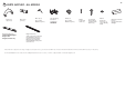
3a PARTS SUPPLIED - ALL MODELS Drain hose support (1) Cavity bracket kit (1) supplied with Tall height Designer and Integrated models only Drain hose joiner (1) Wire clip (1) (for securing Drain hose joiner) Side mounting bracket kit (A and B) (2) OPTIONAL Clamp (1) (for securing Drain hose joiner) Phillips 5⁄8” (16 mm) screws (7) 1½” (38 mm) bottom fixing screws & metal washers (2) Edge Protector (1) (If the services hole is through a metal partition the hole must be protected with the Edge pro
3b ADDITIONAL PARTS SUPPLIED WITH INTEGRATED MODELS External Venting kit (1) Panel bracket (1) (attached to product) Panel mounting screws (6)
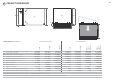
4 PRODUCT DIMENSIONS 6 K H A I Plan G Side D C F J B E Product dimensions 23 9⁄16”(599) 23 9⁄16”(599) 23 9⁄16”(599) 23 9⁄16”(599) 22 15⁄16”(582) 22 ½”(571) 22 ½”(571)3 22 ½”(571)3 21 ¾”(553) 21 ¾”(553) 21 ¾”(553) 21 ¾”(553) 21 7⁄8”(556) 21 7⁄16”(545) 3 21 7⁄16”(545) 21 7⁄16”(545)3 5⁄8 - 13⁄16 ”(16-20) 1 1⁄8”(29) 11⁄16”(18) 5⁄8 - 13⁄16 ”(16-20) 5⁄8 - 13⁄16 ”(16-20) 16 1⁄8”(410) 16 1⁄8”(410) 17 7⁄8”(454) 17 7⁄8”(454) 17 7⁄8”(454) 17 7⁄8”(454) 1 5⁄8”(41) n/a n/a 1 5⁄8”(
5 CABINETRY DIMENSIONS 7 M L Cabinetry dimensions inches (mm) STANDARD HEIGHT MODELS inside depth of cavity 23 5⁄8”(600) 23 5⁄8”(600) 23 5⁄8”(600) 23 5⁄8”(600) 23 5⁄8”(600) min. 22 1⁄16”(560) min. 22 1⁄16”(560) min. 22 1⁄16”(560) min. 22 1⁄16”(560) min. 22 1⁄16”(560) Tall height Classic models L min.
6 INTEGRATED MODELS ONLY - CUSTOM FRONT PANEL CALCULATIONS 8 FRONT PANEL SPECIFICATIONS min. 1⁄16”(2mm) 5⁄8 - 13⁄16” (16-20 mm) panel thickness Maximum weight of panel: 20 lb (9 kg) Adequately sealed to withstand moisture (122OF/ 50OC @ 80% RH). Because of it being a hot and wet environment generally, the back and sides of the panel should be completely sealed with a waterproof vapour barrier (ie polyurethane) to prevent damage to the panel.
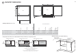
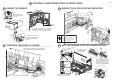
7 OPTIONALLY HARD WIRING PRIOR TO INSTALLATION 7a REMOVE THE DRAWER 9 7b REMOVE THE ACCESS COVER & POWER CORD 43 1 Product may move. Mark chassis position on cavity 4 5 Access cover 6 2 8 To prevent kinked hoses, we recommend rotating the drawer counter-clockwise and resting 5 it on its side after removal. ) 0mmm 4”1(0100 m 3 7 WARNING! Press the release tabs in on either side and push back to release drawer from runners.
8 CAVITY PREPARATION Important! COUNTERTOP These marks indicate formed bracket screw locations, if securing by drawer removal. The power outlet must be located in a cabinet adjacent to the dishwasher cavity. Moisture 3⁄8” (10mm) protection tape must be applied. 110-120 VAC max. 15 A Water Connection Recommended HOT (Maximum 140°F/60°C). Supplied hose to suit 3⁄8” (9 mm) male compression fitting. If there is no side partition, you can construct timber bracing as something to secure into.
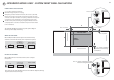
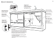
9a INTEGRATED MODELS ONLY - PREPARATION FOR EXTERNAL VENTING THROUGH SAME CABINET Services can be located either side of dishwasher External Venting kit (1) Shelf cutouts max. 3⁄16” (5 mm) VENT HOSE ø max. 1½” (38 mm) ø 2 3⁄8” (60 mm) ø 2 3⁄8” (60 mm) min.4” (100 mm) DRAIN HOSE + INLET HOSE + POWER CORD 8 11⁄16” (220 mm) Important! 4” (100 mm) To prevent pooling of condensation from the vent hose, a toekick height of no less than 4” (100 mm) is required.
10 MAXIMUM DISTANCE OF HOSES & CORD FROM CHASSIS EDGE Left hand side Drain hose - 78 ½" (2000 mm) Inlet hose - 64 ¾" (1650 mm) Power cord (excl. plug) - 29 ½" (750 mm) Venting hose - 60 1⁄16" (1525 mm) (Integrated models only) 12 Right hand side Drain hose - 70 ½" (1800 mm) Inlet hose - 49" (1250 mm) Power cord (excl.
11 DESIGNER & INTEGRATED TALL MODELS FOR 18 7⁄8” (480 mm) CAVITY ONLY - ATTACH CAVITY BRACKET The enclosed cavity bracket is fitted before installation in order to conceal the gap at the top of the cavity left after installation. 1 2 Firmly push the bracket so that the prongs engage with the top tabs and it clicks into place. 1 Important! Ensure the prongs have not been driven down into the chassis as this will damage the lid below.
NOW CHOOSE WHICH INSTALLATION METHOD (a) or (b) IS MORE SUITABLE FOR YOUR CABINETRY... RECOMMENDED METHOD (a) - SECURE WITHOUT DRAWER REMOVAL (FRAMELESS CABINETRY ONLY) 12a ATTACH SIDE MOUNTING BRACKETS Clip all four side mounting brackets into their slots using a flat-bladed screwdriver. Ensure they’re securely fitted before sliding product into cavity.
14a PULL THROUGH HOSES & MOVE INTO THE CAVITY 15 15a SECURE THE DRAWER 1 Vent Hose (Integrated models only) Open the drawer halfway. Using a flat-bladed screwdriver, prize the gray rubber plug out of the trim moulding. Replace the gray rubber plug back into the trim moulding and ensure the trim seal is facing forward. 2 vent either through same cabinet or adjacent cabinet as per step 9a or 9b As you push product in, pull through hoses and cord, ensuring they don’t get kinked or twisted.
ALTERNATIVE METHOD (b) - SECURE BY DRAWER REMOVAL 12b INTEGRATED ONLY - ATTACH VENTING HOSE Check that the fitted elbow is rotated left or right (depending on the direction of the routing), then ensure the venting hose is securely attached to it.
14b REMOVE THE DRAWER 15b SECURE THE DRAWER TO THE CABINETRY 4 1 17 The product has three pairs of fixing points: Product may move. Mark chassis position on cavity Ensure the sound insulation is repositioned correctly. To prevent kinked hoses, we recommend rotating the drawer counter-clockwise and resting it on its side after removal.
INTEGRATED MODELS ONLY - INSTALLING THE FRONT PANEL 18 19 ATTACH PANEL TO PANEL BRACKET 18 REMOVE BRACKET FROM PRODUCT WARNING! Electrical Shock Hazard There must be at least 3 screws used each side Before continuing, ensure that the product is disconnected from the power supply. Failure to follow this warning may result in electrical shock, injury or fire.
INTEGRATED MODELS ONLY - INSTALLING THE FRONT PANEL 22 ADJUST PANEL HEIGHT TO ALIGN THE CABINETRY GAPS + or - 1⁄16” (2 mm) With the front panels fitted, insert an appropriately sized Philips screwdriver into the hole above the door pin and rotate the panels up or down to align the gaps in your cabinetry. Repeat on the other side if necessary. The panel has a maximum travel of 1⁄16” (2 mm) up or down. Important! Ensure that you maintain a minimum of 1⁄16” (2 mm) ventilation gap below the panel.
23 THERE ARE THREE DIFFERENT PLUMBING AND DRAINAGE OPTIONS. CHOOSE WHICH IS MORE SUITABLE. 2 max. max. 4¾” 120 mm (120mm) 1½” 38 mm) mm (38 1 If space is limited for fixing, push hose through drain hose support to required height Supplied drain hose joiner Ø ¾” (19 mm) waste tee 2 3 37 3⁄8” (950 mm) Max. height to top of Air Break (countertop or wall mounted) see 24* 29½”-34¾” (750-882.5 mm) Dishwasher using sink trap with drain hose joiner 2 29 ½”-34 ¾”mm 750-882.5 (750-882.
26 FINAL CHECKLIST 27 TROUBLESHOOTING Excessive water remaining above the filter plate, after the rinse cycle Check for a kinked drain hose or blocked waste connection, highloop not properly installed or drain hose not routed correctly. No water supply (This is displayed as a ‘U1’ fault -- see section ‘If there is a fault’ in the User guide for how to recognise this fault on models without a display.) Check water is connected and turned on. The dishwasher is beeping continuously There is a fault.