
Use and Care Guide


9
INSTALLATION INSTRUCTIONS
EN
HP24 HP36
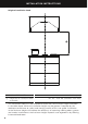
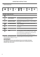
PRODUCT DIMENSIONS
inches (mm) inches (mm)
A
Overall height of product 133/4” (350) 13 3/4” (350)
B
Overall height of product (with
power connection box)
181/4” (463) 181/4” (463)
C
Overall width of product 207/8” (530) 3211/16” (830)
D
Overall depth of product 11” (280) 11” (280)
E
Thickness of flange 1/16” (2) 1/16” (2)
F
Width of chassis 193/8” (492) 313/16” (792)
G
Depth of chassis 101/16” (255) 101/16” (255)
H
Height of side of chassis 711/16” (195) 711/16” (195)
I
Width of top surface of chassis 113/4” (298) 113/4” (298)
J
Length of angled surface of chassis 67/8” (175) 11” (280)
K
Distance from center of ducting
outlet to back of chassis
31/8“ (80) 31/8” (80)
L
Distance from center of ducting
outlet to side of chassis
95/8” (245) 159/16” (395)
M
Diameter of ducting outlet 6” (152) 6” (152)
N
Distance between center of lights 143/4” (375) 269/16” (675)
O
Distance from center of light to
front of product
19/16” (40) 1 9/16” (40)
CABINETRY CUTOUT DIMENSIONS
Overall width of cutout 1911/16” (500) 311/2” (800)
Overall depth of cutout 101/4” (260) 101/4” (260)
P
Base of brackets/clips to bottom of
chassis
min. 9/16” – max. 19/16”
(min. 15 – max. 40)
min. 9/16” – max. 19/16”
(min. 15 – max. 40)
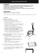
IMPORTANT!
Actual product dimensions may vary by ± 1/16”(2mm).
Please read the entire instructions before installing the ventilation hood.