MR850 RESPIRATORY HUMIDIFIER Technical Manual REVISION J Copyright ©2005 Fisher & Paykel Healthcare Ltd.
Fisher & Paykel Healthcare Head Office: PO Box 14-348, Panmure, Auckland 1134 New Zealand Email: info@fphcare.com Web Site: www.fphcare.com Tel: +64-(0)9-574-0100 Fax: +64-(0)9-574-0158 France/Benelux: Parc Silic-Bal F, 10 Avenue de Quebec, Silic 512 Villebon, 91946, Courtaboeuf, Cedex, France.
TABLE OF CONTENTS 1 INTRODUCTION .................................................................................................................................7 1.1 ABOUT THIS MANUAL..............................................................................................................................7 1.2 GLOSSARY ............................................................................................................................................7 1.3 DEFINITIONS .....................
6 TROUBLESHOOTING ..................................................................................................................... 24 6.1 OPERATIONAL PROBLEMS .................................................................................................................... 24 6.2 TECHNICAL PROBLEMS ........................................................................................................................ 26 6.3 “SEE MANUAL” ERROR CODES .............................................
Revision Description of Technical Manual Change Date Issued A First release technical manual. Covers Revision A PCB’s ONLY. 12 Jan. 1999 B Second release technical manual. Covers Revision C and later PCB’s ONLY. 6 May 1999 C Add “View850” Software Instructions 1 Mar. 2000 D Neonatal volume ventilation capability. 3.4 Performance 4.1.2 Power Up sequence. 4.1.3 Manual Temperature Compensation (TC). 5.3 Cleaning Instructions 15 May 2001 Appendix E – Product Change History.
Revision J Description of Technical Manual Change 1.4 Product Application, Add warning to connect humidifier only to a pure sine wave power source Date Issued 1 November 2005 5.2 Safety Check, add CAUTION: and NOTE: 6.3 “See manual” Error codes, Elaborate the fault description 8.1.5 Humidifier Warm-up and Control Check, Change test flow rate from 20±10 SLPM to 10±5 SLPM. Reference test limits to airway and chamber set temperatures rather than fixed values. 8.2.
Introduction 1.1 About this Manual This manual is intended for qualified service personnel who will perform maintenance and servicing on the Fisher & Paykel Healthcare MR850 Respiratory Humidifier. This manual covers the product specifications, includes a maintenance schedule, and provides the necessary information required for servicing. NOTE: Some software may not be available in your country. Refer to your local Fisher & Paykel Healthcare representative for the appropriate software version.
Expiratory Limb 1.3 The section of the breathing circuit that takes the expired gases from the patient. Definitions NOTE: A NOTE provides important information or explanation of procedures or conditions which may otherwise be misinterpreted or overlooked. CAUTION: A CAUTION statement designates the possibility of damage to this or other equipment if a procedure is not followed exactly.
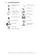
2 Humidifier Symbols Caution: Hot surfaces may exceed 85 °C Power On/Off (stand by) Type BF Invasive Mode Attention – consult accompanying documents Non-invasive mode Alternating Current Temperature Alarm Drip proof protection to IPX1 Serial Port Date of manufacture Protective Earth C-tick for EMC Caution: Electrostatic Sensitive Device Year-month Do not discard WEEE collection (EU only) MR850 Technical Manual * Revision J * Issued November 2005 * Ref.
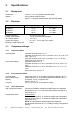
3 Specifications 3.1 Mechanical Dimensions: Weight: 3.2 140 mm x 173 x 135 (without chamber fitted) 2.8 kg (without chamber fitted) Approx. 3.1 kg (with chamber fitted, and filled with water) Electrical MR850 Model Number MR850Axx MR850Pxx MR850Jxx MR850Gxx Supply Voltage 230 V~ 127 V~ 115 V~ 100 V~ Supply Frequency: Heater Plate Capacity HP Thermal Cutout: Heater Wire Supply: Maximum Heater Wire Load: 50 or 60 Hz, Sine Wave 150 W at nominal mains voltage 118 ± 6 °C 22 ± 5 V~, 2.
Non-heater wire operation: Invasive Mode: Airway temperature < 29.5 °C causes an audible and visible alarm. Non-invasive Mode: Airway temperature < 26.0 °C causes an audible and visible alarm. Sound Pressure Level: 3.4 Alarms exceed 50 dBA @ 1 m.
4 Operating Modes and Controls 4.1 Humidifier Operation The MR850 humidifier is designed to add heat and moisture to respiratory gases. The gas is passed through a humidification chamber where it is warmed and humidified. The MR850 has two heating systems. The first is a heater plate, which heats the water contained in the humidification chamber, humidifying the air passing through it.
4.1.2 Non-Heater Wire Operation (Software version 7.23 only) Ventilator/Gas Supply RT134 Breathing Circuit Temperature Probe Chamber Probe Airway Probe MR290 Chamber Water trap MR850 Humidifier Figure 4.2 Typical Non-Heater Wire Humidifier Setup In this application the MR850 maintains the airway temperature at the desired set point (invasive 37 °C or non-invasive 31 °C) by heating the chamber of water through the heater plate.
Stand-by (Software versions: 5.45 & 5.70) • • • • Heater wire power is set at 30 %. Control of chamber temperature is attempted, within the following limits: Heater plate temperature is limited to 60 °C. Heater plate power is limited to 20 %. Stand-by (Software version: 6.00 onward) • • • • Heater wire power is set at 15 %. Control of chamber temperature is attempted, within the following limits: Heater plate temperature is limited to 50 °C. Heater plate power is limited to 20 %.
then the chamber set point will automatically be increased in 0.5 °C steps (1 °C steps for noninvasive mode) until the minimum power is achieved. The maximum amount of compensation applied is either 3 or 5 °C depending on the mode and software version (section 6.4 Diagnostic Menu details how compensation is applied for each software version). If conditions improve and too much power is being applied, then the MR850 will automatically reduce the chamber set temperature.
connected. Breathing circuit recognition is performed via three electrical connections on the heater wire adaptor. Re-configuring the electrical connection pins on a heated circuit and the way it connects to this adaptor identifies the type of heated circuit. In this way three separate heater wire circuits can be identified by the MR850. 4.2 Humidifier Controls 4.2.1 Power Button The humidifier will power on if this button is held down briefly, but must be held for one second to turn the humidifier off.
4.2.3 Mute Button The mute button silences the humidifier's audible alarm. The muted time depends on the alarm condition. In general, alarms will be muted for 2 minutes. A chamber or airway probe alarm is muted for a longer time, until the humidifier determines whether the probe is in or out. The temperature alarm is treated differently - see section 4.5. 4.3 Temperature Display The front panel shows the lower of the chamber or airway temperatures.
4.4.2 Temperature / Flow Probe Connector This indicator will light if the temperature probe is not correctly plugged in, or the probe used is faulty.
4.4.5 Water Out Indicator This indicates that there is insufficient water in the humidification chamber. The humidifier measures the amount of power used to obtain the chamber temperature. If a lower than expected amount of power is used, a 'water out' alarm is generated. It may take 15 minutes or longer to generate an alarm especially if there is a disturbance (change in flow). This alarm can be cancelled by pressing the mute button.
Figure 4.3 Temperature vs Time to Alarm Pressing mute during a temperature alarm silences the alarm for half the normal time period, if the same temperature is maintained. The low temperature warning and alarm can be caused by cold or drafty ambient conditions, or can result from using gas flow rates outside the specification of the breathing circuit, chamber or humidifier. NOTE: The low temperature alarm is disabled in stand-by on software version 5.45 and 5.70. 4.5.
5 Maintenance Procedures In order to keep your humidifier in good working order, it is necessary to perform maintenance at regular intervals. 5.1 Maintenance Schedule 5.1.1 MR850 Humidifier Annually a. Check MR850 for physical damage: • Check the mains cable for damage, replace if necessary. • Check the heater plate for deep scratching etc., replace if necessary. • Check the heater wire adaptor for kinks, abrasions and damaged connectors.
5.2 Safety Check The unit should be tested to the current medical electrical standards for in-house testing for each specific country (example, refer to AS/NZS 3551 for Australia and New Zealand). CAUTION: Permanent damage to this humidifier will result if the serial port is used as a ground point during electrical safety testing. NOTE: The correct ground test point location is on the heater plate front underside edge, as shown in Figure 5.1., where the insulating anodizing layer has been removed.
5.3 Cleaning Instructions 5.3.1 MR850 Humidifiers It is recommended that only the following cleaners be used on the MR850 as at the time of revision of this technical manual. The disinfectants in the list below have been tested to ensure that no damage will result to the outer plastic or metal components of the humidifier. 1. Disconnect the humidifier from any electrical outlet. 2.
6 Troubleshooting 6.1 Operational Problems This section deals with faults that cause the humidifier to alarm. This may be caused by incorrect setup, faulty accessories, or a faulty humidifier. Refer below for troubleshooting. Symptom Corrective Action Reference See manual indicator flashing with audible alarm See manual indicator light permanently on, without an audible alarm Water Out indicator flashes, accompanied by an audible alarm Record the displayed error code. Section 6.3 1.
Symptom Corrective Action Reference Heater wire alarm not working Airway Probe alarm flashes along with an audible alarm Non-heater wire mode has been activated, connect a heated wire circuit or disable this mode via the diagnostic menu. 1. Check that the airway probe is inserted into the breathing circuit correctly, the breathing circuit assembled correctly, and that there is water in the chamber. 2.
Symptom Corrective Action A low temperature is shown on the humidifier’s display, with no audible alarm 1. Make sure the humidifier has had time to warm up and that there is sufficient gas flow through the breathing circuit. 2. The humidifier cannot maintain temperature. If the temperature indicator is also on then an alarm will occur eventually. 3. Humidifier or probe faulty. Complete humidifier and probe performance test. Replace probe or service humidifier as required. 1.
6.3 “See Manual” Error Codes The following is an explanation of the error codes that are displayed in conjunction with the See Manual indicator flashing. A code is not displayed if the microprocessor has stopped functioning (see technical problems - section 6.2). Error E00 E02 E03 E04 E05 E06 E07 E10 E11 E12 E13 E14 E15 E16 E20 E21 E23 E25 E26 E27 E28 E29 E2A E2C E2D E30 E31 E32 E40 Description of Fault No fault Microprocessor stack overflow RAM fault ROM fault EEPROM version older than ROM version.
Error E41 E42 E43 E44 E45 E4A E4B E4C E50 E51 Description of Fault Failed the functional test at time of manufacture Was not stress tested during manufacture Failed the stress test during manufacture Not tested on functional tester 2 Failed production functional tester 2 EEPROM write error occurred EEPROM write verify error occurred EEPROM read error occurred Flow circuitry not functioning Flow circuitry shorted on 28 MR850 Technical Manual * Revision J * Issued November 2005 * Ref.
6.4 Diagnostic Menu By pressing the mute and mode buttons together for 1 second, the diagnostic menu is entered, indicated by the display of two rows of dashes ‘= = =’. Releasing both buttons will allow the diagnostic menu to cycle automatically through the menu, pausing at each function. Pressing the mute button at this time will display the value behind each function for as long as the mute button is held. 6.4.1 Diagnostic Menu for Software Versions 5.45 & 5.
6.4.2 Diagnostic Menu for Software Version 6.00 Display HC Description Humidity Compensation (HC) algorithm Invasive mode, compensation range is 0.0 to 3.0 °C ( CSP = 37.0 to 40 °C ) Non-Invasive mode, compensation range is 0.0 to 5.0 °C ( CSP = 31.0 to 36.0 °C ) By pressing the Mute and Mode buttons together for 1 second or pressing the Mute and Power buttons together for 1 second the user can respectively move up or down through the settings listed below.
6.4.3 Diagnostic Menu for Software Version 7.00 & 7.21 Display HC Description Humidity Compensation (HC) algorithm Invasive mode, compensation range is 0.0 to 3.0 °C ( CSP = 37.0 to 40 °C ) Non-Invasive mode, compensation range is 0.0 to 5.0 °C ( CSP = 31.0 to 36.0 °C ) By pressing the Mute and Mode buttons together for 1 second or pressing the Mute and Power buttons together for 1 second the user can respectively move up or down through the settings listed below.
6.4.4 Diagnostic Menu for Software Version 7.14 Display HC Description Humidity Compensation (HC) algorithm Note: HC is inactive while operating under non-heater wire control. Invasive mode, compensation range is 0.0 to 5.0 °C ( CSP = 37.0 to 42 °C ) Non-Invasive mode, compensation range is 0.0 to 5.0 °C ( CSP = 31.0 to 36.
6.4.5 Diagnostic Menu for Software Version 7.22 Display HC Description Humidity Compensation (HC) algorithm Note: HC is inactive while operating under non-heater wire control. Invasive mode, compensation range is 0.0 to 5.0 °C ( CSP = 37.0 to 42 °C ) Non-Invasive mode, compensation range is 0.0 to 5.0 °C ( CSP = 31.0 to 36.
6.4.6 Diagnostic Menu for Software Version 7.23 Display Cct Description Connected breathing circuit identification: “S“ = Standard inspiratory heater connected “C” = Coaxial inspiratory heater connected “E” = Expiratory heater connected “---” = No heaters detected while under heater wire control Non-Heater Wire Operation To enable non heater wire operation, press and hold both the mute and mode buttons simultaneously for 1 second.
7 Servicing Procedures 7.1 General Considerations WARNING: Although the MR850 display may not be illuminated, the unit may still be energized. Be sure to disconnect the MR850 from the power supply before servicing. All servicing procedures should be followed by a humidifier performance test, and an electrical safety test to ensure proper operation. The performance tests are outlined in section 8.
Figure 7.2 Showing PCB fasteners 7.2.2 Replacing Fuses 1. Open the case (section 7.2.1). 2. The fuses can now be accessed. See Figure 7.3 for the location of the fuses on the power PCB. Figure 7.
MR850 Model Number MR850Jxx Supply Voltage 115 V~ MR850Gxx 100 V~ Fuse Type F1: 1 A 250 V FastBlow F2: 4 A 125 V FastBlow F3: 3 A 250 V FastBlow F4: 3 A 250 V FastBlow F1: 1 A 250 V FastBlow F2: 4 A 125 V FastBlow F3: 3 A 250 V FastBlow F4: 3 A 250 V FastBlow Part Number 999 830 001 999 830 017 999 830 012 999 830 012 999 830 001 999 830 017 999 830 012 999 830 012 WARNING: Be sure to replace the fuse with the correct rating and type.
Figure 7.4 Showing Humidifier Power PCB wiring 7.2.4 Replacement of Transformer 1. Open the case (section 7.2.1). 2. Disconnect the transformer primary and secondary harnesses attached to the power PCB. 3. Unscrew the four mounting screws fixing the transformer, and remove the transformer from the case. 4. Place the new transformer inside the case, and mount using the four screws. 5. Connect transformer primary and secondary harnesses to the power PCB. 6. Close the case (section 7.2.8). 7.2.
3. If the thermal cutout "clicks" when pushed, it has been previously activated, and is now reset. NOTE: If the heater plate is still hot, it must be allowed to cool sufficiently before the thermal cutout will reset. 4. Close the case (section 7.2.8). Replacing the heater plate thermistor NOTE: A Heater plate thermistor service kit is required. (Part Number: 043 041 254) 1. Open the case (section 7.2.1). 2.
Figure 7.7 Showing location of Heater Plate Thermistor Thermal Cutout and Element Screws 8. Solder the wires from the new harness to the heater plate thermal cutout. 9. Attach the cable ties provided to the heater plate harness. 10. Place heater plate back into position, ensuring the springs underneath the heater plate are in place. Attach to the humidifier's case using the three long screws that were previously removed. 11.
5. Remove the heater element, leaving the mica insulator in place. 6. Insert the new element into position, making sure the insulating mica is between the element and the heater plate. 7. Replace the element cover, using the four screws that were previously removed. 8. Replace the element reflector, making sure the washers that separate the reflector from the cover are placed back into position. Screw into place. 9.
7.2.6 Installing New Software NOTE: A software upgrade kit is required. Some software may not be available in your country. Refer to your local Fisher & Paykel Healthcare representative for the appropriate part number: GJU model JHU model All other models Single ROM pack 043042459 043042458 043042066 32 ROM Pack 043042461 043042460 043041255 Figure 7.8 Showing location of U3 1. 2. 3. 4. 5. Open the case (section 7.2.1). Remove ROM integrated circuit U3 (Figure 7.8) using appropriate tools.
6. Apply mains power to the humidifier, while keeping the production test button depressed. The display should read: “PTS”. This ensures that the new software version number will be properly updated in the EEPROM. 7. Turn off the mains power to the humidifier, and remove the tool. 8. Check that the humidifier powers up normally, and complete a full performance test (section 8). (An alternative method for software versions 7.21 onward.) 1. Perform steps 1 to 4 as above. 2.
8 Performance Testing This section discusses the performance testing of the MR850 humidifier and also the MR850 temperature / flow probe. Performance testing is required as part of ongoing maintenance or after servicing of the humidifier has been completed. 8.1 Humidifier Performance Testing If the humidifier has been operating normally, but a performance check is required as part of the maintenance schedule, it is recommended that the following tests are completed: 1.
1. Hold down the power button, then apply mains power to the humidifier. This action places the humidifier into service mode. 2. Select service mode number 1 (Calibration Probe #1 Check) by pushing the mute button when '-1-' is displayed. 3. Insert the calibration probe with the GREY collet into the temperature / flow probe socket of the humidifier. 4. Allow the display to stabilize for a few seconds, and check the number shown on the humidifier display.
8.1.4 Humidifier Voltage Calibration Check This check is required when the humidifier's PCBs have been serviced or replaced, or if the mains transformer has been replaced. Equipment Required: • • • An AC voltmeter, capable of measuring RMS mains voltage to ±0.5 % accuracy. Suitable breathing circuit for MR850 (for example 900RT100). MR850 Heater Wire Adaptor (for example 900MR800). 1. Connect a breathing circuit to the humidifier with the heater wire adaptor.
3. Connect the humidifier chamber inlet to the gas supply, and turn the humidifier on. 4. Wait approximately 30 minutes for the humidifier to stabilise. Chamber and Airway temperatures can be checked by using the display mode (section 4.3.1) and set temperatures can be checked by using the diagnostic menu (section 6.4). After the humidifier has had time to warm up, the temperature at the airway and chamber should be within +0.3 to -1.8°C of their set point, with no alarms occurring.
1. Perform a humidifier calibration check as outlined in section 8.1.2 (ignore this step if recently completed). 2. Set up the humidifier as shown in Figure 4.1. Make sure the chamber probe is correctly inserted into the breathing circuit. 3. Connect the humidifier chamber inlet to the gas supply. 4. Enter the service menu (refer section 8.1.1). 5. Select service mode number 5 (Flow Accuracy Check) by pushing the mute button when '-5' is displayed. 6. Plug the probe under test into the humidifier.
9 Recommended Maintenance Checklist This sheet can be copied and used to keep a record of the maintenance procedures carried out on your MR850 Humidifier(s), and probes. Place the serial number and the date that the maintenance was carried out in the spaces provided. Refer to section 5 for a description of the maintenance procedures required. 9.1 Humidifier Check (Annually) Serial Number Visual Checks 1. Mains Cable 2. Heater Plate 3. Heater Wire Adaptor 9.2 Performance Checks 1.
(Blank) 50 MR850 Technical Manual * Revision J * Issued November 2005 * Ref.
10 Spare Parts Should any parts of the humidifier require replacement, the following parts list is provided. Refer to the exploded diagram on the opposite page for part identification.
MR850 Technical Manual * Revision J * Issued November 2005 * Ref.
Heater Plate Assembly Item Part Number Description 1 614 040 861 Screw (M4x12) 2 641 040 829 Reflector 3 336 060 149 Reflector Spacer Washers 4 641 040 707 Element Cover 5 331040 114 Mica Insulator 6 614 040 327 Thermistor Screw 7 614 040 117 Earth Strap Screw 8 622 040 130 Earth Strap Washer 9 095 428 320 Earth Strap 10 655 040 111 Aluminium Heater Plate 11 349 040 052 Thermal Cutout 12 043 041 254 Thermistor Assembly Kit 13 614 040 327 Thermal Cutout Screw 14 043
MR850 Technical Manual * Revision J * Issued November 2005 * Ref.
11 Calibration Probe The information presented here refers to the construction of the MR850 Calibration Probe. This information is provided so that the probe can be checked for correct operation if required. The calibration probe consists of two Redel plugs, each containing four 0.1 % tolerance resistors. In order to measure the absolute accuracy of these resistors; it is recommended that an ohm meter with better than ± 0.2 % accuracy is used.
12 12.1 Serial Port & Logging Software INTRODUCTION The View850 software* is intended for use with the Fisher & Paykel Healthcare MR850 Respiratory Humidifier. The software can be used to display humidifier data and log the results to a file. A serial cable, part number 900MR888*, is required in order to link the MR850 humidifier to a PC. WARNING: The serial port must not be used when the humidifier is in patient use.
12.3.2 Logging Humidifier Data to File The View850 software can log the data it receives to a text file. This text file can then be opened at a later date (by programs such as Microsoft Excel), in order to review humidifier performance. In order to log the humidifier data, first start the program running. Next set the directory you want the log files to be placed in, by using the menu buttons. Select a directory, and then click on the `OK' button.
13 EMC INFORMATION WARNING: The use of accessories other than those specified by Fisher & Paykel Healthcare may result in increased emissions or decreased immunity of the equipment or system. Guidance and manufacturer’s declaration – electromagnetic emissions The MR850 is intended for use in the electromagnetic environment specified below. The customer or the user of the MR850 should assure that it is used in such an environment.
Guidance and manufacturer’s declaration – electromagnetic immunity The MR850 is intended for use in the electromagnetic environment specified below. The customer or the user of the MR850 should assure that it is used in such an environment.
14 Product Change History Due to upgrades performed on delivered MR850 Respiratory Humidifiers, software and hardware versions are listed below. It should be realised that possible future upgrades may change the operation of the Humidifier. Please note that software Versions 4.40 and 4.44 will only work with Revision A or B PCB’s and Version 5.12 or later will only work with Revision C, D or E PCB’s. History Change for model JHU PCB Version Software Version Introduction A 4.
History Change for model GJU PCB Version Software Version Introduction Serial Number A 4.40 19 September 1998 A 4.44 22 October 1998 C 5.12 12 April 1999 C 5.13 5 May 1999 D 5.13 14 January 2000 2000-85xxx00028 Release of new PCB to improve manufacture. D 5.23 3 April 2000 2000-85xxx01661 Software upgrade for low flow control stability. D 5.33 25 July 2000 2000-85xxx02806 Software upgrade, allowing Neonatal volume ventilation capability.
History Change for all model except JHU & GJU PCB Version Software Version Introduction A 4.40 19 September 1998 A 4.44 22 October 1998 C 5.12 12 April 1999 C 5.13 5 May 1999 D 5.13 14 January 2000 2000-85xxx00028 Release of new PCB to improve manufacture. D 5.23 3 April 2000 2000-85xxx01661 Software upgrade for low flow control stability. D 5.33 25 July 2000 2000-85xxx02806 Software upgrade, allowing Neonatal volume ventilation capability.