Installation instructions and User guide Freestanding cooker OR60 models NZ AU
Contents Safety and warnings Installation instructions Using your oven for the first time Using your oven Cooking functions Using your gas cooktop Cooktop troubleshooting Care and cleaning Warranty and service Important! SAVE THESE INSTRUCTIONS The models shown in this User Guide may not be available in all markets and are subject to change at any time. For current details about model and specification availability in your country, please go to our website www.fisherpaykel.
2 Safety and warnings Installation WARNING! Electrical Shock Hazard Always disconnect the cooker from the mains electricity supply before carrying out any maintenance operations or repairs. Failure to do so may result in death or electrical shock. WARNING! Cut Hazard Take care - panel edges are sharp. Failure to use caution could result in injury or cuts. Important safety precautions General To avoid hazard, follow these instructions carefully before installing or using this product.
Safety and warnings The switch must always be accessible. The power supply cable must not touch any hot parts and must be positioned so that it does not exceed 75 OC at any point. To connect the cooker to the mains, do not use adapters, reducers or branching devices as they can cause overheating and burning. This cooker must be connected to a suitable double pole control unit adjacent to the cooker. No diversity can be applied to this control unit.
4 Safety and warnings Operation Your freestanding cooker has been carefully designed to operate safely during normal cooking procedures. Please keep the following guidelines in mind when you are using it: WARNING! Explosion Hazard Do not store flammable materials such as gasoline near the cooktop. Do not store flammable material in the oven or drawer. Do not spray aerosols near the cooktop during use. Failure to do so may result in death or serious injury.
Safety and warnings 5 Important safety precautions Isolating switch: make sure this cooker is connected to a circuit which incorporates an isolating switch providing full disconnection from the power supply. Household appliances are not intended to be played with by children. Children, or persons with a disability which limits their ability to use the appliance, should have a responsible person to instruct them in its use.
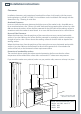
6 Installation instructions Clearances Installation clearances and protection of combustible surfaces shall comply with the current local regulations eg. AG 601 (AS 5601) Gas Installations code. Installation shall comply with the dimension in Fig. 1 bearing in mind that: Overhead Clearances In no case shall the clearances between the highest part of the cooker be less than 600 mm or, for an overhead exhaust fan, 750 mm.
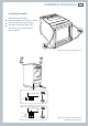
Installation instructions 7 Levelling the cooker To fit the adjustable feet: Place the cooker on its back as shown. Screw the four feet to the cooker. Stand the cooker and level it by screwing or unscrewing the feet with a spanner.
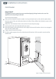
8 Installation instructions Anti-tilt bracket Important! This appliance must be restrained to prevent accidental tipping by fitting a bracket to the rear of the appliance and securely fixing it to the wall. To fix the anti-tilt bracket: After you have located where the cooker is to be positioned mark, on the wall, the place where the two screws of the anti-tilt bracket have to be fitted. Please follow the indications given in the drawing below.
Installation instructions 9 Gas supply The gas connection must be carried out by an authorised person according to the relevant standards. Before connecting the appliance to the gas main, mount the brass conical adaptor onto the gas inlet pipe, upon which the gasket has been placed (see figures following). Conical adaptor and gasket are supplied with the appliance (packed with conversion kit for use with Natural gas or LPG gas). This appliance is suitable for use with Natural Gas or LPG gas.
10 1 Installation instructions After installing the freestanding cooker and connecting the gas supply: Using a suitable leak detection fluid solution (e.g. Rocol) check each gas connection one at a time by brushing the solution over the connection. The presence of bubbles will indicate a leak. If there is a leak, tighten the fitting and then recheck for leaks. Important! 2 3 Do not use a naked flame to test for leaks.
Installation instructions 11 Converting to a different gas type This appliance is suitable for use with Natural gas or LPG gas (check the “gas type” sticker attached to the appliance). To convert from one gas type to another, you need to replace the injectors, and then adjust the minimum burning setting. Replacing the injectors To replace the injectors: Remove pan supports and burners from the cooktop.
12 Installation instructions Adjusting the minimum burner setting Check whether the flame spreads to all burner ports when the burner is lit with the gas tap set to the minimum position. If some ports do not light, increase the minimum gas rate setting. Check whether the burner remains lit even when the gas tap is turned quickly from the maximum to the minimum position. If the burner does not remain lit, increase the minimum gas rate setting.
Installation instructions Lubrication of the gas taps A qualified technician must lubricate the gas taps. Wiring diagram Cod.
14 Using your oven for the first time Front left (auxiliary) burner knob Temperature indicator light Function Temperature knob knob Rear right (semirapid) burner knob Rear left (semi-rapid) Front right burner knob (triple-ring wok) burner knob Figure 11 Control panel 1 2 3 Before using your new oven, please: Read this user guide, taking special note of the ‘Safety and warnings’ section. Remove all accessories and packaging. Condition the oven: Slide in the shelves and grill pan as shown.
Using your oven 15 Figure 13 Function and temperature knobs 1 2 3 Select the function using the function knob. The oven light will come on. Select the temperature using the temperature control knob. The oven temperature indicator light, above the temperature knob on the control panel, will glow until the oven has reached the set temperature, and then it will go out. When you have finished cooking, turn the function and temperature control knobs to the off O position.
16 Cooking functions OVEN LAMP Only the oven light comes on. It remains on in all the cooking functions. BAKE The upper and lower heating elements come on. BAKE is the traditional method of cooking. It is best to cook on only one shelf at a time in this function. FAN BAKE The upper and lower heating elements and the fan come on. FAN GRILL Both the grill and the fan come on. Use with the oven door closed and the temperature knob between 50 °C and 175°C.
Using your gas cooktop 17 2 2 1 3 Figure 15 Cooktop layout 1 2 3 Auxillary burner Semi-rapid burner Triple-ring wok burner Gas burners The knob controls the flow of gas through the safety tap. 0 = closed valve = maximum aperture or flow = minimum aperture or flow You can choose to cook at any heat between and , but never between Figure 16 Burner control knob and 0.
18 Using your gas cooktop Before using your cooktop Before using your new cooktop, please: Read this user guide, taking special note of the safety and warnings section. Turn the cooker on. Make sure all controls are turned off. Lighting the cooktop 1 2 3 Choose the control knob for the burner you want to use. Press the knob down gently and turn it anticlockwise to the position. The ignitors on all the burners will spark. Adjust the flame anywhere between the and positions.
Using your gas cooktop 19 If the cooktop does not light If the cooktop does not light, check that: The cooktop is plugged in and the electricity is switched on. The gas is turned on. The ignitors are sparking. If the ignitors are not sparking, they may be dirty or wet. Clean them with a toothbrush and methylated spirits, as shown. Ignitor Figure 17 Cleaning the ignitor.
20 Using your gas cooktop Choosing a burner Use flat-bottomed pans, and make sure that they match your burner, as shown in the following table. A small pot on a large burner is not efficient.
Cooktop troubleshooting Problem Possible solutions My cooktop burners do not light Check the cooker is switched on. Check the gas supply valve is turned on and the supply to the house is working. You should hear the gas when you turn a burner on. The ignitors may be dirty. Clean them with a toothbrush and methylated spirits. The burner parts may not be located properly. Check the assembly and make sure the burner cap is sitting flat.
22 Care and cleaning Important! Before you start cleaning your cooker, please: Read these cleaning instructions and the ‘Safety and warnings’ section at the start of this user guide. Turn the cooker off at the wall. Make sure the cooker is a safe temperature to touch. Do not use a steam cleaner. Do not keep flammable substances in the oven. General advice Wipe out the oven after every use. Wipe up spills. Avoid leaving alkaline or acidic substances (such as lemon juice or vinegar) on the surfaces.
Care and cleaning 23 Burner parts and pan supports You can remove and clean these parts with hot soapy water or non-abrasive detergents. Clean spills regularly before they become burnt on. Do not wash these parts in a dishwasher. After cleaning, check that the burners and their flame spreaders are dry before replacing correctly. It is very important to check that the burner flame spreader and the cap have been correctly positioned. Failure to do so can cause serious problems.
24 Care and cleaning Replacing the wok burner To replace the wok burner, fit the burner ring to the housing as shown by the arrow in the figure following. Make sure the burner is not able to rotate. Ignitor Figure 23 Replacing the triple ring wok burner Figure 22 Triple ring wok burner parts Gas taps If you have problems with the gas taps, call your Authorised Service Centre.
Care and cleaning 25 Cleaning the enamel cavity Clean the enamel on the inside of the oven when it has cooled down, using household detergents or an ammonia-based cleaner. You may use ‘off the shelf’ oven cleaners, if you carefully follow the manufacturers’ instructions. To make cleaning easier, you can remove the side racks, the oven door, and the fat filter. The grill element is self-cleaning. Cleaning the fat filter Clean the fat filter after every use.
26 Care and cleaning Removing the oven door The oven door can easily be removed as follows: Open the door completely. Hook the swivel retainers of the rh and lh hinges (Fig. 28a) onto the metal bar above them (Fig. 28b). Lift the oven door slightly. The notch on the bottom of the hinge will disengage (Fig. 28c). Now pull the oven door forwards off the appliance. Release both hinge sections from the slots (Fig. 28d). Fig.28a To replace the door, repeat the above steps in reverse order. Fig.28b Fig.
Care and cleaning 27 Replacing the oven lamp Let the oven cavity and the heating elements cool down. Remove the protective cover B. Unscrew and replace the bulb A with a new one suitable for high temperatures (300°C) with the specifications: 230-240V 50 Hz, 15W, E14 Refit the protective cover. Note: Oven bulb replacement is not covered by your warranty.
28 Warranty and service Before you call for service or assistance ... Check the things you can do yourself. Refer to the installation instructions and your user guide and check that: 1 2 Your product is correctly installed. You are familiar with its normal operation. If after checking these points you still need assistance, please refer to the Service & Warranty book for warranty details and your nearest Authorised Service Centre, or contact us through our website: www.fisherpaykel.
Copyright © Fisher & Paykel 2007. All rights reserved. The product specifications in this booklet apply to the specific products and models described at the date of issue. Under our policy of continuous product improvement, these specifications may change at any time. You should therefore check with your Dealer to ensure this booklet correctly describes the product currently available. www.fisherpaykel.com NZ AU Freestanding cooker user guide Published: 02/2007 Part No. 599376 A Elba Part No.