COMPANION PRODUCTS Warming Drawer WB24 Coffee Maker EB24 Steam Oven OS24N models INSTALLATION GUIDE US CA 591496A 11.
CONTENTS Warming drawer 1 Coffee maker 13 Steam oven 21 1 Safety and warnings 2 1 Safety and warnings 14 1 Safety and warnings 22 2 Parts supplied 3 2 Parts supplied 15 2 Prior to installation 23 3 Prior to installation 3 3 Prior to installation 15 3 After installation 23 4 Product dimensions 4 4 After installation 15 4 Product dimensions 24 5 Product dimensions 16 5A Cabinetry dimensions (18 1/8” (460mm) high cavity) 25 5B Cabinetry dimensions (18 7/8” (480mm)
WARMING DRAWER WB24 models
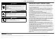
1 SAFETY AND WARNINGS IMPORTANT SAFETY INSTRUCTIONS! WARNING! Electrical Shock Hazard Before carrying out any work on the electrical section of the appliance, it must be disconnected from the mains electricity supply. Connection to a good earth wiring system is absolutely essential and mandatory. Alterations to the domestic wiring system must only be made by a qualified electrician. Failure to follow this advice may result in electrical shock or death.
2 PARTS SUPPLIED Screws (4) Anti-tip bracket (1) Oven support brackets (2) 3 PRIOR TO INSTALLATION ● ● ● ● ● ● The The The The The You cavity is square and level, and of the required dimensions. installation will comply with all clearance requirements and applicable standards and regulations. power switch will be easily accessible to the customer when the warming drawer is installed. warming drawer (and any product on top of it) will rest on a surface that can support its weight.
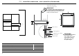
4 PRODUCT DIMENSIONS D B C I A F G SIDE FRONT E Terminal Block D PRODUCT DIMENSIONS C J A Overall height of product B Overall width of product C Depth of drawer front panel (excluding handle)* K D Depth of chassis (including terminal block) E Width of chassis at rear PLAN H F Height from bottom drawer panel to bottom of chassis at rear G Height from bottom of drawer panel to top of chassis H Depth of drawer (open) (measured from front of drawer) I Height of drawer front panel J Depth o
THE FOLLOWING PAGES DETAIL COMMON CABINETRY SCENARIOS 5A CABINETRY DIMENSIONS – UNDERBENCH (ie INSTALLED WITH F&P SINGLE OVEN) N ** O Oven 28 3/8” (720mm) Oven Oven support brackets M Warming drawer *PO PLAN Warming drawer Fit the supplied oven support brackets Tab SIDE Unscrew-fitrescrew Oven support bracket CABINETRY DIMENSIONS inches (mm) M Minimum inside height of cavity 27” (687) N Inside width of cavity 22” (560) O Minimum inside depth of cavity 22 1/4” (565) Note: When installed
5B CABINETRY DIMENSIONS – WALL MOUNTED (ie INSTALLED WITH A F&P COMPACT OVEN) N Compact oven O M 23 5/8” (600mm) Warming drawer *PO Compact oven PLAN SIDE Warming drawer Compact oven Lower trim kit (optional, supplied separately) M Warming drawer Additional 11/16” (18mm) Wood Spacer Cabinet below CABINETRY DIMENSIONS M Minimum inside height of cavity with optional Lower trim kit fitted without optional Lower trim kit fitted inches (mm) 23 1/4” (590) 22 1/2” (570) N Inside width of cavit
5C CABINETRY DIMENSIONS – WALL MOUNTED (ie INSTALLED WITH A F&P COFFEE MAKER) IMPORTANT! If installing under the F&P Coffee Maker, ensure there is the 2” (50mm) gap at the back of the cabinet and the 7 7/8”2 (200mm2) toekick cutout required for airflow. Refer to the Coffee Maker Install instructions.
5D CABINETRY DIMENSIONS – WALL MOUNTED (STANDALONE) Supplied anti-tip bracket (screwed to the back wall) IMPORTANT! In a standalone wall mounted installation, you must ensure that the supplied anti-tip bracket is installed unless there is a fixed shelf above acting as an anti-tip obstacle.
6 DISCARD PACKAGING RESPONSIBLY Unpack the warming drawer and inspect for any signs of damage. Do not install the warming drawer if it has been damaged. IMPORTANT! Packing materials (eg plastic bags, polystyrene foam, staples, packing straps etc) and tools should not be left around during and after installation, especially if they are within easy reach of children, as they may cause serious injuries.
9 SECURE THE WARMING DRAWER TO THE CABINETRY 1 Ensure the warming drawer is level and positioned in place in the cavity. IMPORTANT! Do not lift the warming drawer by the drawer handle. 2 Fully open the drawer. 3 Fasten the warming drawer in place with the two screws supplied, through the front trim, beneath the drawer. Do not overtighten the screws.
!1 FINAL CHECKLIST TO BE COMPLETED BY THE INSTALLER F Make sure the warming drawer is level and securely fitted to the cabinetry. F Make sure any internal packaging has been removed from the drawer. F Make sure that the isolating switch is accessible by the customer. F Make sure the anti-tip bracket has been fitted correctly if it is required. F If installing an oven directly on top of the warming drawer, make sure the supplied oven support brackets have been fitted to the warming drawer.
COFFEE MAKER EB24 models
1 SAFETY AND WARNINGS IMPORTANT SAFETY INSTRUCTIONS! ● Installation ● WARNING! Cut Hazard Take care – some edges are sharp. Failure to use caution could result in injury or cuts. MAINTENANCE ● ● ● ● ● Checking for transport damage After removing the packaging, make sure the product is complete and undamaged and that all accessories are present. Do not use the appliance if it is visibly damaged. Contact Customer Care.
2 PARTS SUPPLIED Screws (7) Rails (2) Clip (1) Spacers (4) for side (4) for bottom 3 PRIOR TO INSTALLATION ● ● ● ● ● ● ● ● ● The countertop and coffee maker cavity are square and level, and are the required dimensions. The installation will comply with all clearance requirements and applicable standards and regulations. The isolating switch will be easily accessible to the customer with the coffee maker installed.
5 PRODUCT DIMENSIONS E H C F D SIDE TOP B I EB24 MODELS PRODUCT DIMENSIONS A Overall height of product A FRONT 18” (458) B Overall width of product 23 1/2” (596) C 18 7/8” (480) Overall depth of product (excluding dials) D Height of chassis 17 1/2” (445) E Width of chassis 22 1/16” (560) F Depth of chassis 18 1/8” (460) G Depth of coffee maker frame and control panel H Stepdown control panel to chassis I Height of control panel 16 | COFFEE MAKER INSTALLATION GUIDE inches (mm) 13/
6A CABINETRY DIMENSIONS (18 1/8” (460mm) HIGH CAVITY) Verify the minimum measurements required for correct installation of the appliance. The coffee maker must be installed in a column and the column must be firmly fixed to the wall with commercially available brackets. IMPORTANT! PROUD INSTALL All installation or maintenance operations must be performed with the appliance disconnected from the mains electricity supply.
6B CABINETRY DIMENSIONS (18 7/8” (480mm) CAVITY TRIM KIT) Verify the minimum measurements required for correct installation of the appliance. The coffee maker must be installed in a column and the column must be firmly fixed to the wall with commercially available brackets. Lower Trim Kit The Lower Trim kit shown is available to order separately from fisherpaykel.com. To install the trim kit, refer to the instructions which accompany it.
7 INSTALLATION INSTRUCTIONS 1/16” (2mm) approx. 13 3/4” (350mm) 1 Position the rails on the sides of the cabinet. Fix with the screws provided, then extract them completely. ● If the coffee maker is installed over a warmer drawer, use the top surface of this as a reference to position the rails. ● In this case, there will be no surface to rest the rails on. ● Position and fix the lock hook with the four screws provided, as shown in the figure. 2 Fix the power cable with the clip.
8 FINAL CHECKLIST TO BE COMPLETED BY THE INSTALLER F Make sure the coffee maker is level and securely fitted to the cabinetry. F Check the lower trim is undamaged. F Check there is adequate clearance. This is to ensure correct air circulation. F Make sure any cable ties and internal packaging has been removed from the coffee maker cavity. F Make sure all coffee maker vents and openings are clear and free of any obstruction or damage.
STEAM OVEN OS24N models
1 SAFETY AND WARNINGS IMPORTANT SAFETY INSTRUCTIONS! Installation WARNING! Electrical Shock Hazard Before carrying out any work on the electrical section of the appliance, it must be disconnected from the mains electricity supply. Connection to a good ground wiring system is absolutely essential and mandatory. Alterations to the domestic wiring system must only be made by a qualified electrician Failure to follow this advice may result in electrical shock or death.
2 PRIOR TO INSTALLATION ● ● ● ● ● ● ● ● ● The countertop and oven cavity are square and level, and are the required dimensions. The installation will comply with all clearance requirements and applicable standards and regulations. The isolating switch will be easily accessible to the customer with the oven installed. The electrician provides sufficient free length of power supply cable to reach from the bottom rear of the cavity to at least 59 1/16” (1.5m) in front of the bottom edge of the opening.
4 PRODUCT DIMENSIONS E C F D G H TOP SIDE B OS24N MODELS PRODUCT DIMENSIONS A Overall height of product A B Overall width of product C Overall depth of product (excluding handle and dials) 23 7/16” (596) 22 1/8” (562) 17 1/2” (445) E Width of chassis 21 7/8” (556) F Depth of chassis 21 1/4” (540) 7/8” (22) (=distance between front of chassis and front of oven door, excl.
5A CABINETRY DIMENSIONS (18 1/8” (460mm) HIGH CAVITY) The oven can be installed under a cooktop, in a column, or combined with the companion warmer drawer. The cabinet material must be able to withstand heat. The oven must be centered within the walls of the cabinet and fixed with the screws and bushings that are provided.
5B CABINETRY DIMENSIONS ● ● ● (18 7/8” (480mm) CAVITY TRIM KIT) The oven must be installed under a cook top, in a column, or combined with the companion warmer drawer. The cabinet material must be able to withstand heat. The oven must be centred within the walls of the cabinet and fixed with the screws and bushings that are provided. Lower Trim Kit The Lower Trim kit shown is available to order separately from fisherpaykel.com. To install the trim kit, refer to the instructions which accompany it.
6 ELECTRICAL HOOK-UP ● ● Before connecting to the electricity, make sure that the: specifications of the electrical system match with what is detailed on the serial number plate applied to the front of the oven. system has an effective ground connection compliant with current standards and laws. The ground connection is required by law. The cable must not, at any point, reach a temperature greater than 122°F (50°C) above room temperature.
8 FINAL CHECKLIST TO BE COMPLETED BY THE INSTALLER F Make sure the oven is level and securely fitted to the cabinetry. F Check the lower trim is undamaged. F Open the oven door slowly until it is fully open and check there is adequate clearance between the bottom of the door and the lower trim. This is to ensure correct air circulation. Should the lower trim become damaged, straighten the trim and ensure the oven door opens fully without obstruction.
PRODUITS COMPAGNONS Modèles Tiroir chauffant WB24 Machine à café EB24 Four à vapeur OS24N GUIDE D’INSTALLATION CA 591496A 11.
CONTENTS Tiroir chauffant 1 Machine à café 13 Four à vapeur 21 1 Sécurité et avertissements 2 1 Sécurité et avertissements 14 1 Sécurité et avertissements 22 2 Pièces fournies 3 2 Pièces fournies 15 2 Avant l’installation 23 3 Avant l’installation 3 3 Avant l’installation 15 3 Après l’installation 23 4 Dimensions du produit 4 4 Après l’installation 15 4 Dimensions du Produit 24 5 Dimensions du produit 16 5A Dimensions de l’armoire (cavité de 18 1/8” (460mm) de ha
TIROIR CHAUFFANT Modèles WB24
1 SÉCURITÉ ET AVERTISSEMENTS CONSIGNES DE SÉCURITÉ IMPORTANTES AVERTISSEMENT! Danger de choc électrique Avant d’effectuer tout travail sur la partie électrique de l’appareil, celui-ci doit être déconnecté du secteur. La connexion à un bon système de mise à la terre est absolument essentielle et obligatoire. Les modifications apportées au système de câblage domestique ne doivent être effectuées que par un électricien qualifié. Le non-respect de ce conseil peut entraîner un choc électrique ou la mort.
2 PIÈCES FOURNIES Des vis (4) Support anti-basculement (1) Supports de support de four (2) 3 AVANT L’INSTALLATION ● ● ● ● ● ● La cavité est carrée et de niveau, et des dimensions requises. L’installation sera conforme à toutes les exigences de dégagement et aux normes et règlements applicables. L’interrupteur d’alimentation sera facilement accessible au client lorsque le tiroir-réchaud est installé.
4 DIMENSIONS DU PRODUIT D B C I A F G LE CÔTÉ AVANT E Bornier D DIMENSIONS DU PRODUIT C A Hauteur totale du produit J 4 5/8” (118) 13/16” (20) 7/8” (22) D Profondeur du châssis (y compris le bornier) 21 1/8” (536) 21 1/8” (536) E Largeur du châssis à l’arrière 21 3/4” (551) 21 3/4” (551) G Hauteur entre le bas du panneau du tiroir et le haut du châssis H Profondeur du tiroir (ouverte) (mesurée depuis l’avant du tiroir) I Hauteur du panneau avant du tiroir J Profondeur de la poigné
LES PAGES SUIVANTES DÉTAIL SCÉNARIOS D’ARMOIRES COMMUNES 5A DIMENSIONS DE L’ARMOIRE – UNDERBENCH (ie INSTALLÉ AVEC F&P FOUR UNIQUE) N ** O Four 28 3/8” (720mm) Four Supports de support de four M Tiroir chauffant *PO HAUT Tiroir chauffant Monter les supports de four fournis Attache LE CÔTÉ CABINETRY DIMENSIONS Dévisseradapter-rescrew M Hauteur intérieure minimale de la cavité 27” (687) N Largeur intérieure de la cavité 22” (560) O Profondeur intérieure minimale de la cavité Support de four
5B DIMENSIONS DE L’ARMOIRE – MURAL (ie INSTALLÉ AVEC UN FOUR COMPACT F&P) N Four compact O M 23 5/8” (600mm) Tiroir chauffant *PO Four compact HAUT LE CÔTÉ Tiroir chauffant Four compact M Trousse de garniture inférieure (en option, fournie séparément) Tiroir chauffant Espaceur de bois supplémentaire de 11/16” (18mm) Cabinet ci-dessous CABINETRY DIMENSIONS Pouces (mm) M Hauteur intérieure minimale de la cavité avec kit de garniture inférieur en option sans kit de garniture inférieur en opt
5C DIMENSIONS DE L’ARMOIRE – MURAL (ie INSTALLÉ AVEC UNE CAFETIÈRE F&P) IMPORTANT! Si vous installez sous la cafetière F&P, assurez-vous qu’il y a un espace de 2”(50mm) à l’arrière de l’armoire et une découpe de 7 7/8”2 (200mm2) pour le passage de l’air. Reportez-vous aux instructions d’installation du fabricant de café.
5D DIMENSIONS DE L’ARMOIRE – MURAL (STANDALONE) Support anti-basculement fourni (vissé sur la paroi arrière) IMPORTANT! Dans une installation murale autonome, vous devez vous assurer que le support antibasculement fourni est installé à moins qu’une étagère fixe agisse au-dessus comme un obstacle anti-basculement.
6 JETER L’EMBALLAGE DE MANIÈRE RESPONSABLE Déballez le tiroir chauffant et inspectez pour déceler tout signe de dommage. N’installez pas le tiroir chauffant s’il a été endommagé. IMPORTANT! Les matériaux d’emballage (sacs en plastique, mousse de polystyrène, agrafes, sangles d’emballage, etc.) et les outils ne doivent pas être laissés en place pendant et après l’installation, surtout s’ils sont facilement accessibles aux enfants, car ils peuvent causer des blessures graves.
9 FIXEZ LE TIROIR CHAUFFANT AUX ARMOIRES 1 Assurez-vous que le tiroir chauffant est de niveau et positionné dans la cavité. IMPORTANT! Ne soulevez pas le tiroir chauffant par la poignée du tiroir. 2 Ouvrez complètement le tiroir. 3 Fixez le tiroir chauffant en place avec les deux vis fournies, à travers la garniture avant, sous le tiroir. Ne pas trop serrer les vis.
!1 LISTE DE CONTRÔLE FINALE A REMPLIR PAR L’INSTALLATEUR F Assurez-vous que le tiroir-réchaud est de niveau et solidement fixé aux armoires. F Assurez-vous que tout emballage interne a été retiré du tiroir. F Assurez-vous que l’interrupteur d’isolement est accessible au client. F Assurez-vous que le support anti-basculement a été correctement installé si nécessaire.
MACHINE À CAFÉ Modèles EB24
1 SÉCURITÉ ET AVERTISSEMENTS CONSIGNES DE SÉCURITÉ IMPORTANTES! Installation ENTRETIEN ● ● AVERTISSEMENT! Couper le danger Attention – certains bords sont coupants. Ne pas faire preuve de prudence peut entraîner des blessures ou des coupures. ● ● ● ● ● Vérification des dommages de transport Après avoir retiré l’emballage, assurez-vous que le produit est complet et non endommagé et que tous les accessoires sont présents. N’utilisez pas l’appareil s’il est visiblement endommagé.
2 PIÈCES FOURNIES Des vis (7) Rails (2) Agrafe (1) Espaceurs (4) pour le côté (4) pour le bas 3 AVANT L’INSTALLATION ● ● ● ● ● ● ● ● ● La cavité du comptoir et de la cafetière sont carrées et de niveau, et sont les dimensions requises. L’installation sera conforme à toutes les exigences de dégagement et aux normes et règlements applicables. L’interrupteur d’isolement sera facilement accessible au client avec la cafetière installée.
5 DIMENSIONS DU PRODUIT E H C F D LE CÔTÉ HAUT B I MODÈLES EB24 DIMENSIONS DU PRODUIT A Hauteur totale du produit A 23 1/2” (596) C 18 7/8” (480) Profondeur totale du produit (à l’exclusion des cadrans) D Hauteur du châssis 17 1/2” (445) E Largeur du châssis 22 1/16” (560) G Profondeur du cadre de la cafetière et du panneau de commande H Panneau de contrôle Stepdown au châssis I Hauteur du panneau de contrôle 16 | COFFEE MAKER INSTALLATION GUIDE 18” (458) B Largeur totale du produit
6A DIMENSIONS DE L’ARMOIRE (CAVITÉ DE 18 1/8” (460MM) DE HAUTEUR) Vérifiez les mesures minimales requises pour une installation correcte de l’appareil. La cafetière doit être installée dans une colonne et la colonne doit être fermement fixée au mur avec des supports disponibles dans le commerce. IMPORTANT! Toutes les opérations d’installation ou de maintenance doivent être effectuées avec l’appareil déconnecté du secteur.
6B DIMENSIONS DE L’ARMOIRE (KIT DE GARNITURE DE CAVITÉ DE 18 7/8” (480MM)) Vérifiez les mesures minimales requises pour une installation correcte de l’appareil. La cafetière doit être installée dans une colonne et la colonne doit être fermement fixée au mur avec des supports disponibles dans le commerce. Trousse de garniture inférieure Le kit Lower Trim montré est disponible à commander séparément auprès de fisherpaykel.com.
7 INSTRUCTIONS D’INSTALLATION 1/16” (2mm) environ 13 3/4” (350mm) 1 Positionnez les rails sur les côtés de l’armoire. Fixer avec les vis fournies, puis les extraire complètement. ● Si la cafetière est installée sur un tiroir chauffant, utilisez la surface supérieure comme référence pour positionner les rails. ● Dans ce cas, il n’y aura pas de surface sur laquelle reposer les rails. ● Positionnez et fixez le crochet de verrouillage avec les quatre vis fournies, comme indiqué sur la figure.
8 LISTE DE CONTRÔLE FINALE A REMPLIR PAR L’INSTALLATEUR F Assurez-vous que la cafetière est de niveau et solidement fixée aux armoires. F Vérifiez que la garniture inférieure n’est pas endommagée. F Vérifiez qu’il y a un dégagement suffisant. Ceci afin d’assurer une circulation d’air correcte. F Assurez-vous que les attaches de câble et l’emballage interne ont été retirés de la cavité de la cafetière.
FOUR À VAPEUR Modèles OS24N
1 SÉCURITÉ ET AVERTISSEMENTS CONSIGNES DE SÉCURITÉ IMPORTANTES! Installation AVERTISSEMENT! Danger de choc électrique Avant d’effectuer tout travail sur la partie électrique de l’appareil, celui-ci doit être déconnecté du secteur. La connexion à un bon système de mise à la terre est absolument essentielle et obligatoire. Les modifications apportées au système de câblage domestique ne doivent être effectuées que par un électricien qualifié.
2 AVANT L’INSTALLATION ● ● ● ● ● ● ● ● ● Le comptoir et la cavité du four sont carrés et de niveau, et sont les dimensions requises. L’installation sera conforme à toutes les exigences de dégagement et aux normes et règlements applicables. L’interrupteur d’isolement sera facilement accessible au client avec le four installé. L’électricien fournit suffisamment de longueur libre du câble d’alimentation pour atteindre l’arrière de la cavité à au moins 59 1/16” (1.
4 DIMENSIONS DU PRODUIT E C F D G H HAUT LE CÔTÉ B MODÈLES OS24N DIMENSIONS DU PRODUIT A A Hauteur totale du produit 18” (458) B Largeur totale du produit 23 7/16” (596) C Profondeur totale du produit (à l’exclusion de la poignée et des cadrans) 17 1/2” (445) E Largeur du châssis 21 7/8” (556) F Profondeur du châssis 21 1/4” (540) 7/8” (22) (=distance entre l’avant du châssis et l’avant de la porte du four, à l’exclusion des boutons) H Profondeur de la porte du four lorsqu’elle est co
5A DIMENSIONS DE L’ARMOIRE (CAVITÉ DE 18 1/8” (460MM) DE HAUTEUR) Le four doit être installé sous une table de cuisson, dans une colonne ou combiné avec le tiroir-réchaud. Le matériau de l’armoire doit être capable de résister à la chaleur. Le four doit être centré dans les parois de l’armoire et fixé avec les vis et les bagues fournies.
5B DIMENSIONS DE L’ARMOIRE (KIT DE GARNITURE DE CAVITÉ DE 18 7/8” (480MM)) ● ● ● Le four doit être installé sous une table de cuisson, dans une colonne ou combiné avec le tiroir-réchaud. Le matériau de l’armoire doit être capable de résister à la chaleur. Le four doit être centré dans les parois de l’armoire et fixé avec les vis et les bagues fournies. Trousse de garniture inférieure Le kit Lower Trim montré est disponible à commander séparément auprès de fisherpaykel.com.
6 BRANCHEMENT ÉLECTRIQUE ● ● Avant de vous connecter à l’électricité, assurez-vous que: les spécifications du système électrique correspondent à ce qui est détaillé sur la plaque de numéro de série appliquée à l’avant du four. le système a une connexion au sol efficace conforme aux normes et lois en vigueur. La connexion au sol est requise par la loi. Le câble ne doit à aucun moment atteindre une température supérieure à 122 ° F (50 ° C) au-dessus de la température ambiante.
8 LISTE DE CONTRÔLE FINALE A REMPLIR PAR L’INSTALLATEUR F Assurez-vous que le four est de niveau et solidement fixé aux armoires. F Vérifiez que la garniture inférieure n’est pas endommagée. F Ouvrez lentement la porte du four jusqu’à ce qu’elle soit complètement ouverte et vérifiez qu’il y a un espace suffisant entre le bas de la porte et la garniture inférieure. Ceci afin d’assurer une circulation d’air correcte.