
installation guide

3
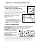
5. TOOLS RECOMMENDED FOR INSTALLATION
• PhillipsScrewdriver • 1-1/2"WoodBitorMetalHoleCutter(ifmetalcabinetisused)
• ElectricDrill • 1/2",5/8"and3/32"DrillBits
• Scissors • Sawtocutexhaustopening(ifneeded)
• Pencil • Measure
• Tape • ProtectiveDropClothforproductandrange—youmayalso
use carton for protection
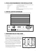
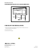
6. INSTALLATION HARDWARE
TheINSTALLATIONHARDWARE(items1-8)packedwiththeovenshouldcontainthefollowing:
ITEM NAME QUANTITY PART CODE
1
Wood Scr
ew 5 x 30 mm 6 290109
2
Toggle Bolt #10 - 24 x 50 mm 4 290106
3
Top Cabinet Screw 5 x 60 mm 2 290108
4
Flat Washer 30 mm diameter 2 290107
5
Grommet 1 290105
6
Tapping Screw 4 x 12 mm 8 245657
7
Exhaust Damper Assembly 1 290046
8
Mounting Deector 1 290122
1 5
6 7
2 3 4
8
Figure 5
7. PREPARATION OF THE OvEN
1. Open the bottom of the carton, remove oven and all packing materials.
2. CHECK THE OVEN.
Check the oven for any damage, such as misaligned or bent door,
damaged door seals and sealing surfaces, broken or loose door
hinges and latches and dents inside the cavity or on the door.
If there is any damage, do not operate the oven and contact
your dealer or Fisher & Paykel AUTHORIZED SERVICER.
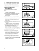
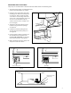
3. Rest the microwave oven on its side as shown in Figure 6.
4. Remove the two screws which secure the mounting plate
to the rear side of the oven. Remove the mounting plate.
The
two screws can be discarded.
Note: If the unit you purchased does not have the mounting
plate attached to the rear side of the oven, please disregard
this section and continue to Section 8.
Mounting plate
Grease lter openings
Figure 6