Gas Dryer DGGX1US Installation instructions
WARNING For your safety the information in this manual must be followed to minimize the risk of death, personal injury, fire, explosion, or property damage. Do not store or use gasoline or other flammable vapors and liquids near this or any other appliance. What to do if you smell gas Do not try to light or start any appliance. Do not touch any electrical switch; do not use any telephone in your building. Clear the room, building or area of all occupants.
Important safety instructions WARNING To reduce the risk of fire, electric shock, or injury to persons when using your appliance, follow basic precautions, including the following: 1. Read all instructions before using the appliance. 2. Installation and service must be performed by a qualified installer, service agency or the gas supplier. 3. Make sure the power cord is located so that it will not be stepped on, tripped over or otherwise subject to stress or damage. 4.
Read this before you start installing your dryer This is the safety alert symbol. This symbol alerts you to hazards that can kill or hurt you and others. The safety alert symbol and the word DANGER or WARNING will precede all safety messages. These words mean: DANGER You can be killed or seriously injured if you don’t immediately follow instructions. WARNING You can be killed or seriously injured if you don’t follow instructions.
To the installer The correct installation of the dryer is your responsibility. Be sure you read the following instructions carefully before you start to install the dryer. These instructions should be left with the home owner for future reference. It is your responsibility to: Observe all governing codes and ordinances. Check code requirements. Some codes limit or do not permit installation of clothes dryers in garages, closets, mobile homes or sleeping quarters.
The area in which the dryer is located must be kept clear and free from combustible materials, gasoline and other flammable vapours and liquids. A dryer produces combustible lint so the area around the dryer must be cleaned regularly to keep it free of lint. This dryer can only be vented from the rear and must be exhausted to the outdoors. Alcove or closet installation WARNING When installing a dryer in a closet/alcove it must be exhausted to the outdoors.
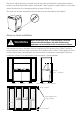
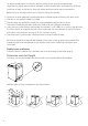
Dimensions Lid clearance �� ���� � �� ����� ���� � ������ �� ���� � �� ����� ����� � ������� ��� ����� � ������� Check that there is enough clearance for the lid to fully open.
Mobile home installation The installation of the dryer in a mobile home must conform to the Manufactured Home Construction and Safety Standard Title 24 CFR, Part 32-80 {formerly the Federal Standard for Mobile Home Construction and Safety, Title 24 HUD (Part 280), 1975} for the United States. When installing a dryer in a mobile home, provisions for anchoring the dryer to the floor must be made. A Mobile Home Installation kit is available with instructions (see Accessories page 4).
Exhausting The dryer must be exhausted to the outdoors. This will prevent the build up of lint and moisture in the room in which it is located and reduce the risk of fire. WARNING Fire Hazard The dryer must be vented to the outdoors. Use rigid or thick wall flexible metal exhaust duct. Do not use a plastic exhaust duct. Do not use a metal foil exhaust duct. Failure to follow these instructions can result in death or fire. This appliance must always be vented to the outdoors.
To reduce condensation, insulate any ducting which passes through unheated areas. Slope the duct gently downwards to the hood, to drain condensation and reduce lint build up. Avoid sag or loops in the duct as they may collect and store water and accumulate lint. Before using an existing exhaust duct system for a dryer ensure that: No plastic or other potentially combustible duct or flexible metal foil ducting has been used. The duct is not pierced, kinked or crushed.
Choose a route that will provide the straightest and most direct path outdoors. Plan the installation to use the fewest number of elbows and turns. When using elbows (rigid duct) or making turns (thick wall flexible metal duct), allow as much room as possible. With thick wall flexible metal duct bend duct gradually to avoid kinking and avoid 90˚ turns.
Preferred 4” Hoods When you have a 4” (10cm) Hood Maximum length of 4” diameter metal duct. Number of 90˚ elbows/bends Thick Wall Flexible Metal (fully extended) Rigid 0 64ft 19.5m 36ft 10.9m 1 54ft 16.5m 31ft 9.4m 2 44ft 13.4m 27ft 8.2m 3 35ft 10.6m 25ft 7.6m 4 27ft 8.2m 23ft 7.0m Acceptable 2 1⁄2”Hood When you have a 2 1⁄2” (6cm) Hood Maximum length of 4” diameter metal duct. Number of 90˚ elbows/bends Rigid Thick Wall Flexible Metal (fully extended) 0 58ft 17.
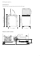
Alternative installation for close clearances Venting systems come in many varieties. Select the type best for your installation. A close-clearance installation is shown. swivel collar wall connection sections separate, fittings can face same or opposite swivel collar Extra long band–clamp for dryer connection telescoping sections beveled edges allow corner installations The maximum length using a 2” x 6” (5cm x 15cm) rectangular duct with two elbows and a 2 1⁄2”(6.3cm) exhaust hood is 8ft (2.4m).
Exhaust venting WARNING Fire Hazard Use heavy metal exhaust duct. Do not use a plastic exhaust duct. Do not use thin metal foil exhaust duct. Failure to do so can result in death or fire. 1. Read the exhaust section (page 9–13) before installing the exhaust system to determine the maximum allowable exhaust duct length. Do not use sheet metal screws when assembling ducting. Always use suitable duct tape. Never use plastic or thin metal foil flexible exhaust material. 2.
Installation Parts and literature are packaged inside the dryer drum. WARNING Excess Weight Hazard Use two or more people to move and install the dryer. Failure to do so can result in back or other injury. Only remove the packaging at the customer’s premises. This will ensure the appliance arrives in pristine condition and reduces the risk of damage when transporting to the customer’s home. Unpacking Make sure dryer is in a suitable location for installation.
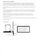
Fitting the front feet Note: Dryer is usually supplied with feet fitted and protruding the correct distance. 1. Tilt the dryer back using a hand trolley and making sure the trolley and dryer are secure. 2. Fit a rubber insert to each plastic foot as shown. 3. Screw the feet into the foot retainers on the left hand and right hand sides as shown. 4. Screw both feet in so they protrude 1⁄2” (12mm) below the bottom of the wall on the foot retainers.
Electrical requirements WARNING Electrical Shock Hazard Plug into a grounded 3-prong outlet. Do not remove ground prong. Do not use an adaptor. Do not use an extension lead. Failure to follow these instructions can result in death, fire, or electrical shock. Grounding instructions This appliance must be grounded. In the event of malfunction or breakdown, grounding will reduce the risk of electric shock by providing a path of least resistance for electric current.
Gas requirements The installation must conform with Local Codes, or in the absence of Local Codes, to the National Fuel Gas Code ANSI/Z223.1, Latest Revision (for the United States). WARNING Explosion Hazard Use a new AGA or CSA approved gas supply line. Install a shut-off valve. Securely tighten all gas connections. If connecting to LP Gas, have a qualified person make sure gas pressure does not exceed 13” (33 cm) water column.
Connecting gas to your dryer Use compound or thread tape appropriate to the gas type that is to be used (Natural or LP Gas), on the male threads of all non-flared connections. Never use an open flame to test for gas leaks. This dryer will operate satisfactorily up to altitudes of 6500ft (2000m) above sea level at the BTU rating indicated on the model/serial plate. Burner input adjustments may be required if operating above this elevation.
Connecting to the dryer 4. To connect the dryer to the gas supply, a number of options and types of connections can be used, such as rigid piping or tubing, or if local codes permit, new flexible tubing. 5. If flexible tubing is used, an elbow should be installed on the pipe at the back of the dryer for the flexible tube to be connected to. This will minimise damage to the tube when the dryer is moved back. Use a flexible tubing connection kit that has designed for use on a clothes dryer.
Level machine Check the dryer is level, and make necessary adjustments to the front levelling feet. The rear levelling feet are self adjusting. Final installation check list Check that: No plastic or flexible metal foil is used in the exhaust ducting. Exhaust is rigid ducting or thick wall flexible metal ducting. All joints in the ducting are made with duct tape – no screws are used. Ducting is clean and is connected to the dryer. Inserts are fitted to the two front feet.
Copyright Reserved © Fisher & Paykel 2004. The product specifications in this booklet apply to the specific products and models described at the date of issue. Under our policy of continuous product improvement, these specifications may change at any time. You should therefore check with your Customer Care Center to ensure this booklet correctly describes the product currently available. www.fisherpaykel.com US Installation Instructions Published: 03/2004 Part No.