MAN 4275A00 PN: 00275-8026-0001 English July 2000 P r oduc tDi s c ont i nue d HART® Communicator
Product Manual for the HART Communicator NOTICE Read this manual before working with this product. For personal and system safety, and for optimum product performance, make sure you thoroughly understand the contents before using or servicing this product. For equipment service needs, contact the nearest product representative. Rosemount and SMART FAMILY are registered trademarks of Rosemount Inc. MINIGRABBER is a trademark of Pomona Electronics.
TABLE OF CONTENTS The HART® Communicator............................................... 1-1 Introduction........................................................................................ 1-1 HART Communicator Connections ................................................... 1-2 Liquid Crystal Display (LCD) ............................................................. 1-5 The Action Keys ................................................................................ On/Off Key ..........................
Delete Configs Menu....................................................... System Information Menu ....................................................... Listen for PC Menu ................................................................. Storage Location Menu ........................................................... Simulation Menu ..................................................................... 1-25 1-26 1-26 1-28 1-28 Saving a Connected Device Configuration......................................
Menu Trees ....................................................................... 3-1 Introduction........................................................................................ 3-1 Model 54pH/ORP Transmitter ......................................................... 3-2 Model 333 HART® Tri-Loop Converter ............................................ 3-3 Model 644 Temperature Transmitter................................................ 3-4 Model 1151 Pressure Transmitter .............................
Model APEX Radar Level Gauge................................................... 3-33 Model ProBarTM DP Flowmeter .................................................... 3-34 Model ProBarTM UC Flowmeter .................................................... 3-35 Model Tri-20/9000 Oval Flowmeter ................................................ 3-36 Model WC3000 Oxygen Analyzer .................................................. 3-37 HART Communicator Messages ......................................
Section LIST OF ILLUSTRATIONS Figure Number Title Page 1-1. The HART Communicator. .......................................................... 1-1 1-2. Rear Connection Panel with NiCad Recharger Jack. ................. 1-2 1-3. Connecting to the Transmitter Comm Terminals. ....................... 1-3 1-4. Connecting the HART Communicator to the Loop. ..................... 1-3 1-5. Connecting the HART Communicator with the Load Resistor. ... 1-4 1-6. HART Communicator Alphanumeric and Shift Keys. ........
1-30. Delete Configurations Menu. ..................................................... 1-25 1-31. System Information Menu. ........................................................ 1-26 1-32. Listen for PC Menu. .................................................................. 1-26 1-33. Storage Location Menu. ............................................................ 1-28 1-34. Sample Hot Key Menu. ............................................................. 1-30 1-35. Hotkey Configuration Menu. ......
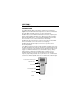
SECTION 1 The HART® Communicator INTRODUCTION The HART (Highway Addressable Remote Transducer) Communicator (Figure 1-1) is a hand-held interface that provides a common communication link to all HART-compatible, microprocessor-based instruments. Section 1 discusses the HART Communicator Connections, Liquid Crystal Display, Keypad, Offline and Online menu, Battery Pack, Memory Module, data pack 100, Maintenance, and Year 2000 Compatibility.
HART COMMUNICATOR CONNECTIONS The HART Communicator can interface with a transmitter from the control room, the instrument site, or any wiring termination point in the loop through the rear connection panel (Figure 1-2). To interface, connect the HART Communicator with the appropriate connectors in parallel with the instrument or load resistor. All connections are non-polarized. When connecting to a PC, you must use the PC Communication Adapter to connect to the Communicator’s serial port.
NOTE: For the HART Communicator to function properly, a minimum of 250 ohms resistance must be present in the loop. The HART Communicator does not measure loop current directly. Figure 1-3 and Figure 1-4 illustrate typical wiring connections between the HART Communicator and any compatible device. HART-compatible Device RL≥250 Ω _ + + _ _ + + mA _ _ + + Power Supply _ Current Meter FIGURE 1-3. Connecting to the Transmitter Comm Terminals.
! WARNING Explosions can result in death or serious injury. Before connecting the HART Communicator in an explosive atmosphere, make sure the instruments in the loop are installed in accordance with intrinsically safe or nonincendive field wiring practices. For intrinsically safe CSA and FM wiring connections, see Appendix C. Figure 1-5 shows how to connect the optional 250 ohm load resistor. NOTE: To temporarily install the optional 250 ohm Load Resistor: 1.
LIQUID CRYSTAL DISPLAY (LCD) The LCD is an 8-line by 21-character display that provides communication between you and the connected device. When you connect to a HARTcompatible device, the top line of each Online menu displays the model name of the device and its tag. The bottom line of each menu is reserved for the dynamic labels for each software-defined function key, F1-F4 (found directly below the display). These dynamic labels display available functions.
Up Arrow Key Use this key to move the cursor up through a menu or list of options. You can also use it to scroll through lists of available characters when editing fields that accept both alpha and numeric data. Down Arrow Key Use this key to move the cursor down through a menu or list of options. You can also use it to scroll through lists of available characters when editing fields that accept alpha and numeric data.
In menus providing access to the Home menu, the HOME label appears above the F3 key. When the HOME label displays, press F3 to return directly to the Online menu. Press BACK (F3) to return to the screen from which HOME was pressed. Table 1-1 describes the labels that appear above each function key throughout the various Communicator menus. TABLE 1-1. Function Key Labels.
ALPHANUMERIC AND SHIFT KEYS The 12 alphanumeric keys (Figure 1-6) perform two functions — the fast selection of menu options and data entry. Three shift keys enable use of the upper row of characters on each alphanumeric key. FIGURE 1-6. HART Communicator Alphanumeric and Shift Keys.
Using Shift Keys for Data Entry Some menus require data entry. Use the up and down arrow keys when available, or use the alphanumeric and shift keys to enter the alphanumeric information into the HART Communicator. If you press only the alphanumeric key within an edit menu, only the bold character in the center of the key will display. These large characters include the numbers zero through nine, the decimal point (.), and the dash symbol (-).
Power Supply 5ø ø 12.øø 1øø Online Menu Main Menu FIGURE 1-8. Powering Up Offline or Online. Software Icons The HART Communicator menus display icons that represent specific keys on the keypad. Figure 1-9 shows examples of these. HART communication: Blinking indicates ongoing communications (HART messages are presently being transmitted or received). Blinking indicates the device is configured in the burst mode.
Learning the Menu Structure The following steps show you how to power up the Communicator offline, move through the menu structure, and then turn off the Communicator: ➊ Turn the HART Communicator on. ➋ Access the Utility menu by pressing three times and then pressing ➌ Access the Configure Communicator menu from the Utility menu by pressing ➍ Access the Contrast menu by pressing once and then pressing ➎ Press ESC (F3) to return to the Configure Communicator menu.
Reviewing Installed Devices The HART Communicator Memory Module contains device descriptions for specific HART-compatible devices. These descriptions enable the Communicator to recognize particular devices. The device types can be found in the Offline menu under New Configurations. If you cannot find a specific HART-compatible device on your Communicator, the device revision you are looking for is not programmed into the Memory Module.
If the Communicator is powered up when it is connected to a device, you can access the Main menu by pressing the previous menu key. Depending on the current online menu, you may need to press the previous menu key several times or the HOME key plus to return to the Main menu. OFFLINE MENU From the Main menu, press 1 to access the Offline menu. From the Offline menu you can access the options: New Configuration and Saved Configuration. Figure 1-11 shows a menu tree for the Offline functions.
New Configuration (Offline) Use this option to compile a custom set of device configuration data for downloading to any HART-compatible device. You can download repeatedly to multiple devices so that they store identical configuration data. Offline configuration may not be available for all devices. Steps 2 and 3 below will help you verify if the desired manufacturer and device model are programmed into the Communicator’s Memory Module. 1. Press STU 1 on the Main menu to access the Offline menu.
From Blank Template Menu To access From Blank Template Menu, see steps 2 through 5 under New Configuration (Offline) on page 1-14. FIGURE 1-13. From Blank Template Menu. The following options are available from the From Blank Template menu: Mark all flags all configurable variables to be sent to a HART-compatible device. Configuration variables are those that appear when you edit variables in the configuration using the Edit Individually option.
Save as... saves your new configuration to either the Memory Module or the data pack 100. See Figure 1-16 and Figure 1-17. The Memory Module holds up to 10 typical configurations, and contains the operating system software, and device application software in nonvolatile memory. The data pack stores up to 100 typical configurations in nonvolatile removable memory. FIGURE 1-16. Save As... Menu. FIGURE 1-17. Location Menu. You can also use the Save As...
Saved Configuration Menu (Offline) You can access configuration data already stored in your Communicator through the offline Saved Configuration menu. To access configuration data stored in your HART Communicator: 1. Press 1 on the Main menu to access the Offline menu. 2. Press 2 from the Offline menu, and the Saved Configuration menu screen displays (Figure 1-18). FIGURE 1-18. Saved Configuration Menu (Offline). 3.
you entered with Sort by picking characters from the device Tag, Descriptor, or Name. When setting up a filter, you can use the period (.) to replace a single character of any value or the asterisk (*) to replace zero or more alphanumeric characters of any value. For example, if you enter A-*-.1, it should match all device tags starting with A-, followed by any characters, followed by -, followed by any single character, and ending with a 1.
Rename accesses the Configuration Name editing menu. After making name changes, enter and save the data to return to the previous storage location menu. Compare compares a selected device configuration from a stored location with another device configuration. The HART Communicator compares device types, variables, marked lists, etc. Messages will appear indicating whether the configurations compared are the same or different. Press OK to return to the storage location and your list of device configurations.
When the DD for a specific device is not available, your HART Communicator provides a generic interface. This generic interface enables you to perform functions common to all HART-compatible devices. Figure 1-22 shows the Generic Online menu tree. The Online (Generic) menu is the first menu in the generic interface. This menu displays critical, up-to-date device information such as the process variable (PV), analog output (AO), lower range value (LRV), and upper range value (URV).
1 Process Variables 1 Present variable 2 Percent Range 3 Analog Output Self Test 1. Test Device 2 Diagnostics and Service 2. Loop Test 1. Apply Values 2. Enter Values 3. Calibration 4. D/A Trim 1. Tag 2. PV Snsr Unit 3 Basic Setup 3. Range Values 4. Device Info. 5. Xfer Fnctn 6.PV Damp 1 2 3 4 5 6 7 8 Model Tag Date Descriptor Message PV snsr s/n Final Asmbly # Revision 1 Univ Rev. 2 Fld Dev Rev 3 Softw Rev 1. Process Variables 1 Sensors Generic Online Menu 1 2 3 4 5 2. PV Snsr Unit 3.
FREQUENCY DEVICE MENU YZ / 3 From the Main menu, press to access the Frequency Device menu (Figure 1-23). This menu displays the frequency output and corresponding pressure output for the current-to-pressure devices. The output shown below was taken from device Model 3311. FIGURE 1-23. Frequency Device Menu. UTILITY MENU JKL From the Main menu, press 4 to access the Utility menu (Figure 1-24). The Utility menu provides access to functions that affect only the operation of the HART Communicator.
Polling Menu Use the Polling options to configure your HART Communicator to automatically search for all or specific connected devices. The HART protocol allows you to communicate with multiple HART devices on a single twisted pair of wires over leased telephone lines. When several devices are connected in the same loop (multidropped), each device must be assigned a unique address.
Contrast Menu The Contrast menu adjusts the contrast on the LCD. However, the first time you reset and save the contrast, it is entered permanently. When you turn the Communicator off, then on, the adjusted setting will reappear. If you need help, call your service center for assistance. Follow these steps to adjust the contrast: 1. From the Configure Communicator menu, press trast menu (Figure 1-27). VWX 2 to access the Con- FIGURE 1-27. Contrast Menu. 2.
3. To save the off time change, press ENTER (F4) and the Configure Communicator menu displays. Entering Zero (0) will disable this option. The maximum time allowed is 255 minutes. However, be aware that no information will be received about the improper operation of a field device when the Communicator is turned off. Ignore Diagnostics Menu The HART Communicator is designed to display diagnostic messages from a connected device.
System Information Menu From the Utility menu, press (Figure 1-31). VWX 2 to access the System Information menu FIGURE 1-31. System Information Menu. Motherboard system information consists of the Serial Peripheral Interface Time (SPI Time) and the firmware revision number. Module system information consists of hardware and software data. For example, you can find the hardware revision, RAM size, and Flash size; or, the different software revisions and binary sizes.
Follow these steps to connect your HART Communicator to a PC: 1. Plug the PC Communication Adapter into the 9-pin Serial Port located on the back of the Communicator. Refer to Appendix B for an illustration of the PC Communication Adapter and the Communicator. 2. Plug the PC 25-pin Serial Port cable into the other end of the PC Communication Adapter. 3. Connect the PC’s Serial Port cable to the back of the PC.
Storage Location Menu From the Utility menu, press 4 to access the Storage Location menu (Figure 1-33). The Storage Location menu allows you to access the Memory Module or data pack memory permanent storage locations. FIGURE 1-33. Storage Location Menu. The PC option requires AMS software running in your computer. Refer to Listen for PC Menu on page 1-26 for more information.
4. To access the main configuration menu, select the applicable device revision. The Online menu for the simulated device is displayed. You can now use the HART Communicator as if it were connected to the selected device, and perform any online task. If you are unsure of the device revision, connect the HART Communicator to the device and determine its device revision level. This information is most commonly accessed from Online menu>Device Setup>Detailed Setup>Device Information.
6. If you choose not to SAVE data but want to continue, the SEND key will reappear after each selection is entered. 7. Repeat the above process where necessary to modify each device configuration. When saving a new configuration or changing a saved configuration offline, you will not encounter the send key. USING THE HOT KEY The Hot Key menu is a user-definable menu that can hold up to 20 options of your most frequently performed tasks. Figure 1-34 shows a typical Hot Key menu with four added options.
Customizing the Hot Key Menu You can customize the Hot Key menu to provide fast access to Range values and your most frequently used tasks. Range values is a permanent option providing quick access to rerange. This option cannot be deleted from the Hot Key menu. Adding Options to the Hot Key Menu The Hot Key menu has space for up to 20 online options. For example, if you have to change device tags and damping often, you can add these functions to the Hot Key menu.
4. Press ALL (F1) to add the option to the Hot Key menu for all of the HARTcompatible devices supported in your Communicator; or, press ONE (F4) to add the option to the Hot Key menu for the specific device to which you are currently connected. See Figure 1-36. FIGURE 1-36. Adding a Hot Key Option. 5. If the message “Mark as read only variable on Hot Key menu?” Figure 1-37 displays, press YES (F1) to mark the variable for this option as read-only, or press NO (F4) to mark the variable as read/write.
6. Press YES (F1) to display the variable associated with the option on the Hot Key menu, or press NO (F4) to not display it. See Figure 1-39. FIGURE 1-39. Variable Display Option. 7. Press EXIT (F4) on the Hot Key Configuration menu to complete the task. The options are now included on the Hot Key menu. Deleting Options from the Hot Key Menu Use the following steps to delete an online option from the Hot Key menu: 1. Press any one of the three shift keys, release it, and then press the Hot Key.
THE HART COMMUNICATOR AND THE YEAR 2000 The HART Communicator is Year 2000 Compliant if the operating system is level 4.6 or greater. To determine the operating system level in your HART Communicator, turn it on. The first screen displays the “Module Rev”, which is the operating system level. If you need to update your operating system software, contact your nearest product representative. NOTE: When you power up the Communicator, the Firmware Rev number appears first.
SERVICING THE HART COMMUNICATOR As shown in Figure 1-42, the modular construction of the HART Communicator allows easy disassembly of the battery pack, the Memory Module, and the data pack 100. This section discusses how to change alkaline batteries, recharge the NiCad battery pack, upgrade the Communicator software, and install and remove the data pack 100. Replaceable (AA) or optional rechargeable (NiCad) battery pack data pack 100 275-0275K01B Memory Module FIGURE 1-42.
Changing Alkaline Batteries ! WARNING Explosions can result in death or serious injury. Do not remove or replace battery pack in an explosive atmosphere. Refer to Figure 1-43 and use the following steps to change alkaline batteries: FIGURE 1-43. Battery Pack Removal. 1. Completely loosen the three captive screws holding the Communicator battery pack. 2. Grasp the battery pack and pull it away from the Communicator. Make sure not to bend the pins connecting the battery pack to the Communicator. 3.
Recharging the Battery Pack ! WARNING Explosions can result in death or serious injury. Do not recharge the NiCad battery pack in an explosive atmosphere. NiCad battery packs are shipped from the factory discharged. Prior to the first use, charge the battery pack while it is disconnected from the Communicator. Subsequent charges may be performed while using or storing the HART Communicator, without removing the battery pack.
Replacing the Memory Module ! WARNING Explosions can result in death or serious injury. Do not remove or replace battery pack in an explosive atmosphere. Refer to Figure 1-43 and Figure 1-44, and use the following steps to replace the Memory Module: FIGURE 1-44. Memory Module Replacement. 1. Completely loosen the three captive screws holding the Communicator battery pack. 2. Grasp the battery pack and pull it straight up from the Communicator.
Installing and Removing the Data Pack 100 Refer to Figure 1-43, Figure 1-44, and Figure 1-45. Use the following steps to install or remove the data pack: FIGURE 1-45. Data Pack 100 Installation and Removal. To Install the data pack: 1. Remove the battery pack from the Communicator. Next, either remove the Memory Module or leave it assembled to the Communicator. 2.The data pack is keyed to prevent incorrect installation.
1-40
SECTION 2 Common Tasks for Fisher-Rosemount HART Devices INTRODUCTION This section displays HART Communicator menus and describes tasks common to Fisher-Rosemount HART products. POWERING UP ONLINE Powering up online provides direct access to the Online menu. This menu provides critical data that is continuously updated. To be powered online, the Communicator must be connected to a 4–20 mA loop. To power up the Communicator and access a HART compatible device: 1.
ONLINE MENU The Online menu is the first menu to appear when the Communicator is connected to a HART compatible device. This menu is structured to provide important information about the connected device immediately on powering up the Communicator (Figure 2-1). This menu displays critical, up-to-date device information including primary variable, analog output, lower range value, and upper range value. 5ø 12 ø FIGURE 2-1. Online Menu.
Primary Variable (PV) Press VWX 2 to access Primary Variable. The Online menu displays critical process information that is continuously updated. If the PV and related engineering units are too long, they will not appear on the Online menu. Select PV to view primary variable and the related engineering units. Analog Output (AO) Press YZ / 3 to access Analog Output. The analog output is the signal on the 4–20 mA scale that corresponds to the primary variable.
DEVICE SETUP MENU As shown in Figure 2-2, the Device Setup menu contains the following five options: STU Press 1 to access the Device Setup menu from the Online menu. The options on this menu (Figure 2-2) are described in the following paragraphs. FIGURE 2-2. Device Setup Menu. Process Variables Press STU 1 to access the Process Variables menu. This menu lists all process variables and their values. These process variables are continuously updated.
Loop test can fix the transmitter output at a specified analog value, and can be used to test the integrity of the loop and the operation of indicators, recorders, or similar devices in the loop. Calibration can include such operations as configuring output related parameters, performing a sensor trim, or performing an analog output trim. Basic Setup Press YZ / 3 to access the Basic Setup menu.
Review Press MNO 5 to access the Review menu. This menu lists all of the parameters stored in the connected device, including information about the measuring element, signal condition, and output. It also includes stored information about the connected device such as tag, materials of construction, and device software revision. FAST KEY SEQUENCES A fast key sequence is simply a sequence of numerical button presses, corresponding to the menu options that lead you to a given task.
Trimming the analog output is a calibration of the output circuitry, by setting the 4 and 20 mA points. Once the 4 and 20 mA points are set, all intermediate values are automatically adjusted. See Menu Trees in Section 3 for a corresponding menu tree. From the Online menu, select Device setup. 50 12 0 From the Device setup menu, select Diag/ Service. From the Diag/Service menu, select Calibration. From the Calibration menu, select Trim analog output.
2-8
SECTION 3 Menu Trees INTRODUCTION This section displays typical examples of menu trees for specific FisherRosemount products. Menu trees show the primary commands and options available when using a sequence of menu selections. Text displayed in all bold capital letters in the menu trees indicates a progression to the next level. Due to space limitations, all levels may not be shown. Also note that your specific device could be different from the example shown.
Model 54pH/ORP Transmitter 1 PROCESS VARIABLES 1 VIEW FLD DEV VARS 1 2 3 4 5 6 pH ORP Temp Input glass Ref 1 2 3 4 5 SV is pH pH & rnge AO Convention 2 VIEW PV-ANALOG 1 3 VIEW SV-ANALOG 2 4 View alarms 5 View status 1 TEST DEVICE 2 DIAG/ SERVICE 2 Fix analog output PV is pH pH & rnge AO Convention 1 View status 2 View alarms 3 Master reset 1 CALIBRATE PV 3 CALIBRATION 4 Trim analog output 5 Hold mode 1 Tag 3 BASIC SETUP 1 2 3 4 5 2 PV RANGE VALUES 2 ADJUST TEMPERATURE 1 2 3 4 5 pH LRV pH UR
Model 333 HART® Tri-Loop Converter 1 STATUS 1 TEST DEVICE 1 Status group 1 2 Status group 2 2 Reset 2 Loop test 1 DIAG/ SERVICE 3 CALIBRATION 1 CONFIGURE CHANNELS 1 CONFIGURE CH1 2 CONFIGURE CH2 3 CONFIGURE CH3 2 Recall fact trim 4 D/A trim 1 Tag 1 CONFIGURE CH1 2 CONFIGURE CHANNELS 2 CONFIGURE CH2 2 BASIC SETUP 3 CONFIGURE CH3 1 DEVICE SETUP 3 DEVICE INFORMATION 1 OUTPUT CONDITION 3 DETAILED SETUP 2 DEVICE INFORMATION 4 REVIEW 3-3 1 2 3 4 5 6 7 Model Dev id Tag Date Descriptor Message Fina
Model 644 Temperature Transmitter 1 2 3 4 5 1 PROCESS VARIABLES 2 DIAGNOSTIC AND SERVICE Snsr 1 Snsr 1 % Rnge Snsr 1 A/O Output Term Temp VARIABLE MAPPING 1 4 ma 2 20 ma 3 Exit 1 TEST DEVICE 1 Status 2 Self Test 3 Master Test 2 LOOP TEST 1 2 3 4 4 ma 20 ma Other End 1 2 3 4 5 APPLLY VALUES RANGE VALUES SNRS TRIM D/A Trim Scaled D/A Trim 1 2 3 4 Differential Temp Terminal Temp Sensor 1 Sensor 2 3 CALIBRATION 4 Smart Calibration 3 BASIC SETUP 1 PV 2 SV 1 2 3 4 5 6 Tag PV Unit RANGE VALUES
Model 1151 Pressure Transmitter 1 PROCESS VARIABLES 1 Pressure 2 Percent Range 3 Analog Output 1 TEST DEVICE 2 DIAGNOSTICS AND SERVICE 1 Self test 2 Status 1 Keypad Input 2 Apply Values 2 Loop Test 1 RERANGE 3 CALIBRATION 2 TRIM ANALOG OUTPUT 1 Tag 3 SENSOR TRIM 1 Digital-to-Analog Trim 2 Scaled D/A Trim 1 2 3 4 Zero Trim Lower Sensor Trim Upper Sensor Trim Sensor Trim Points 2 Unit 3 BASIC SETUP 3 RANGE VALUES 1 Keypad Input 2 Apply Values 4 DEVICE INFO 1 2 3 4 5 5 Transfer Function 6 Dam
Model 2081C Conductivity Transmitter 1 PROCESS VARIABLE 1 VIEW FIELD DEVICE VARIABLES 1 C 2 Temperature 3 AC 2 VIEW PVANAOLOG 1 1 2 3 4 PV is PV PV % Range PV A/O 3 View Status 2 DIAGNOS AND SERVICE 1 STANDARDIZE COND 2 Loop Test 2 INITIAL SETUP 1 Cell Const.
Model 2081pH Transmitter 1 PROCESS VARIABLE 1 VIEW FIELD DEVICE VARIABLES 1 pH 2 Temperature 3 Input 2 VIEW PVANAOLOG 1 1 2 3 4 PV is PV pH PV % Range PV A/O 3 View Status 2 DIAGNOS AND SERVICE 1 TEST/STATUS 1 View Status 2 Master Reset 2 Loop Test 1 BUFFER CALIBRATION 1 Begin Procedure 2 Slope 3 pH 1 Begin Procedure 2 pH 2 STANDARDIZE ph 3 CALIBRATION 3 ADJUST TEMPERATURE 4 Trim Analog Output 1 2 3 4 5 6 1 Tag 3 BASIC SETUP 2 PV RANGE VALUES PV LRV PV URV PV Damp PV pH PV % Range Xfer Fun
Model 2088 Pressure Transmitter 1 PROCESS VARIABLES 2 DIAG/SERVICE 3 BASIC SETUP 1 Pres 2 % rnge 3 AO 1 TEST DEVICE 2 Loop test 3 CALIBRATION 1 RE-RANGE 1 Keypad input 2 Apply values 1 Tag 2 ANALOG OUTPUT TRIM 1 D/A trim 2 Scaled D/A trim 2 Unit 3 SENSOR TRIM 3 RANGE VALUES 1 Keypad input 2 Apply values 1 2 3 4 5 Zero trim Lower sensor trim Upper sensor trim Snsr trim cal typ SENSOR TRIM POINTS 1 2 3 4 Sel dec pt pos CM Upper Value CM Lower value CM Units 4 DEVICE INFORMATION 5 Damping 1
Model 2090 Pressure Transmitter 1 PROCESS VARIABLES 1 Pres 2 % rnge 3 AO 2 DIAG/SERVICE 1 TEST DEVICE 2 Loop test 3 CALIBRATION 1 Tag 2 Unit 3 RANGE VALUES 1 Self test 2 STATUS 1 RE-RANGE 1 Keypad input 2 Apply values 2 ANALOG OUTPUT TRIM 1 D/A trim 2 Scaled D/A trim 3 SENSOR TRIM 1 2 3 4 5 1 Keypad input 2 Apply values Zero trim Lower sensor trim Upper sensor trim Snsr trim cal typ SENSOR TRIM POINTS 3 BASIC SETUP 4 DEVICE INFORMATION 1 2 3 4 5 DEVICE SETUP PV AO LRV URV 5 Damping 1 2 3 4
Model 3001S Hydrostatic Transmitter 1 PROCESS VARIABLES 2 DIAGNOSTICS AND SERVICE 3 BASIC SETUP 1 2 3 4 Pres % rnge A/O Snsr temp 1 TEST DEVICE 1 Self Test 2 Status 2 Loop Test 1 RE-RANGE 1 Keypad Input 2 Apply Values 3 CALIBRATION 2 TRIM ANALOG OUTPUT 1 D/A Trim 2 Scaled D/A Trim 3 SENSOR TRIM 1 2 3 4 1 2 3 4 5 6 Tag PV Unit Range Values DEVICE INFO Trans Funct Damping 1 SENSORS 1 2 3 4 5 Date Descriptor Message Write Protect Meter Type 1 PRESSURE SENSOR 2 TEMP SENSOR 2 SIGNAL CONDIT
Model 3044C Temperature Transmitter 1 PROCESS VARIABLES 2 DIAGNOSTICS AND SERVICE 1 2 3 4 5 Sensor 1 Sensor 1 Percent Range Sensor 1 Analog Output Electronics Temperature Variable Mapping 1 TEST DEVICE 1 Status 2 Self Test 3 Master Test 2 Loop Test 1 Apply Values 2 Range Values 3 CALIBRATION 1 Sensor Input Trim 2 Sensor Trim-Factory 3 SENSOR TRIM 4 Digital-to-Analog Trim 5 Scaled D/A Trim 3 BASIC SETUP 1 2 3 4 5 6 Tag PV Unit Range Values Connections PV Damp Sensor 1 Sensor s/n 1 Sensor 1 2 Sn
Model 3051 Pressure Transmitter 1 PROCESS VARIABLES 1 Pres 2 % rnge 3 AO 4 Snsr temp 1 Self test 2 STATUS 1 TEST DEVICE 2 DIAG/ SERVICE 3 BASIC SETUP 1 RE-RANGE 1 Keypad input 2 Apply values 3 CALIBRATION 2 ANALOG OUTPUT TRIM 1 D/A trim 2 Scaled D/A trim 1 Tag 2 Unit 3 SENSOR TRIM 4 Recall fact trim 3 RANGE VALUES 1 Keypad input 2 Apply values 1 2 3 4 5 Zero trim Lower sensor trim Upper sensor trim Snsr trim cal typ SENSOR TRIM POINTS 4 DEVICE INFORMATION 1 2 3 4 1 2 3 4 5 Sel dec pt pos
Model 3051C Pressure Transmitter (Original) 1 PROCESS VAR 1 2 3 4 Pressure Percent Range Analog Output Sensor Temperature 1 Self test 2 Status 1 TEST DEVICE 1 RERANGE 2 DIAGNOS AND SERVICE 2 Loop Test 2 TRIM ANALOG OUTPUT 1 Keypad Input 2 Apply Values 1 Digital-toAnalog Trim 2 Scaled D/A Trim 3 CALIBRATION 1 Tag 3 SENSOR TRIM 1 2 3 4 Zero Trim Lower Sensor Trim Upper Sensor Trim Sensor Trim Points 2 Unit 3 BASIC SETUP 1 DEVICE SETUP 2 PV 3 AO 4 LRV 5 URV 3 RANGE VALUES 4 DEVICE INFO 5 Transfer
Model 3081C Conductivity Transmitter 1 VIEW FLD DEV VARS 1 PROCESS VARIABLES 2 VIEW PVANALOG 1 3 Vew status 2 DIAG/ SERVICE 1 TEST DEVICE 2 Loop test 3 CALIBRATION 4 D/A trim 5 Hold mode 1C 2T 3L 4R 5 NaOH 6 HCl 7 H2SO4 low 8 H2SO4 hi 9 Temp 10 A 1 PV is 2C 3T 4L 5R 6 NaOH 7 HCl 8 H2SO4 low 9 H2SO4 hi 10 Cond % rnge 11 AO 1 View status 2 Master reset 3 View history 1 STANDARDIZE PV 2 INITIAL SETUP 1 Tag 3 ADJUST TEMPERATURE 3 BASIC SETUP 2 PV RANGE VALUES 3 DEVICE INFORMATION 1 SENSORS 4 DETAILED
Model 3081FG Oxygen Analyzer 1 PROCESS VARIABLES 1 VIEW FLD DEV VARS 1 O2 value 2 Cell Temp 3 Cell mV 2 VIEW OUTPUT VARS 1 VIEW PV-AOUT 1 2 3 4 2 VIEW SV 1 SV is 2 SV 3 VIEW TV 1 TV is 2 TV 4 VIEW 4V 1 4V is 2 4V 1 Device Status 2 Loop test 2 DIAG/SERVICE 3 O2 CALCHECK 4 D/A trim 1 2 3 4 5 6 Start Calcheck OPtrakTG? HighTG LowTG Slope Constant 5 MAX CELL TEMP PV is O2 value % rnge O2 output 1 Max Temp 2 Reset Max Temp 1 Tag 3 BASIC SETUP 1 DEVICE SETUP 2 PV 3 PV AO 3 LRV 4 URV 5 Device SN
Model 3081pH Transmitter 1 PROCESS VARIABLE 1 VIEW FIELD DEVICE VARIABLES 1 2 3 4 5 6 Ph ORP Temperature Input Glass Ref 2 VIEW PVANAOLOG 1 1 2 3 4 PV is PV PV % Range PV A/O 3 View Status 2 DIAGNOS AND SERVICE 1 2 3 4 1 TEST DEVICE 1 View Status 2 Master Reset 3 View History 2 Loop Test 1 BUFFER CALIBRATION 3 CALIBRATION 2 STANDARDIZE PV 4 Trim Analog Output 3 ADJUSTMENT TEMPERATURE 1 Begin Procedure 2 pH 3 0 Offset 1 2 3 4 5 Hold Mode 1 2 3 4 5 6 1 Tag 3 BASIC SETUP 2 PV RANGE VALUES
Model 3095C Level Controller 1 LEVEL (LV) 1 More Level Setup 2 Level 3 LV Unit 4 Range values 5 LV Damping 6 LV Trim 1 2 3 4 DP DP unit DP Damping DP Sensor Trim 5 Dp USL 6 DP LSL 1 PROCESS VARIABLES 2 PRESSURE (DP) 1 2 3 4 5 RTD PT PT unit PT Damping PT Sensor Trim 6 PT USL 7 PT LSL 3 TEMPERATURE (PT) 1 CONTROL LOOP 2 CONTROLLER 1 2 3 4 5 6 7 2 SETPOINT OPTIONS Level Setpoint Target Mode Manual Ctl Out Anlg sgnl DEVICE SETUP 3 MODE SUPERVISOR 1 More Control Setup 2 P: Gain 3 I: Reset 4 D: Rat
Model 3095MV Multivariable Transmitter 1 PROCESS VARIABLES 1 2 3 4 5 Pres % rnge A/O VIEW FLD DEV VAR VIEW OUTPUT VAR 1 TEST STATUS 2 DIAGNOSTIC AND SERVICE 1 Diff Pres 2 Static Pres 3 Process Temp 1 Loop Test 2 View Status 3 Reset 1 D/A Trim 2 Scaled D/A Trim 3 Factory Trim 2 ANALOG TRIM 3 BASIC SETUP 1 2 3 4 5 DEVICE SETUP PV PV AO PV LRV PV URV 1 OUTPUT CONDITION 1 DP Unit 2 SP Unit 3 Temp Unit 1 2 3 4 5 6 7 8 9 1 DP Snsr Range 2 SP Snsr Range 3 SP Type 4 Isoltr Matrl 5 Fill Fluid 6 Flnge
Model 3144 Temperature Transmitter 1 PROCESS VARIABLES 1 2 3 4 5 6 7 PV Eng Units PV $% Rnge PV A/O Output VIEW FLD DEV VAR SV Variable Mapping VARIABLE RE_MAP 1 Status 2 Self Test 3 Master Test 2 LOOP TEST 1 2 3 4 4 ma 20 ma Other End 1 2 3 4 5 6 7 Apply Values RANGE VALUES SENSOR TRIM D/A Trim Scaled D/A Trim CJC Cal.
Model 3201 Hydrostatic Interface Unit 1 CONSTANTS 1 PRODUCT CONSTANTS 2 TANK CONSTANTS 1 SET UP 2 STRAPPING DATA 3 COMMUNICATIONS 1 ModAdd 2 BaudRt 3 MODBUS SCALING 4 User Reg Map 4 DEVICE TYPES 5 DISPLAY SELECT 8 ANALOG OUTPUT 2 PROC VARIABLE TblSiz StrTmp StrDns Strap Table Edit 1 2 3 4 5 PtType PmType SwType TmpTyp WBType 1 2 3 4 5 6 7 8 9 Mass MeaDen StdDen Volume Level Temp Press Flow XferSP 1 2 3 4 PV is URV LRV OUTPUT TRIM 1 DISPLAY SEL PRIM 2 DISPLAY SEL OTHER 6 UNITS SELECT 7 TRAN
Model 3202 Smart Application Module 1 CONSTANTS 1 SET UP 2 STRAPPING TABLE 3 COMMUNICATIONS 1 PRODUCT CONSTANTS 2 TANK CONSTANTS 1 2 3 4 TblSiz StrTmp StrDns STRAPPING TABLE 1 ModAdd 2 BaudRt 3 MODBUS SCALING 4 USER ASSIGN REG 4 DEVICE TYPES 1 PtType 2 PmType 3 TmpTyp 5 DISPLAY SELECT 1 DISPLAY SEL PRIM 2 DISPLAY SEL OTHER 6 UNITS SELECT 7 ANALOG OUTPUT 1 2 3 4 PV is URV LRV OUTPUT TRIM 1 CALCULATED DATA 2 PROC VARIABLE 2 MEASURED DATA 3 ALARMS 4 TEST 5 DEVICE INFO 6 AUTO/MANUAL 1 TEST
Model 3244 Temperature Transmitter 1 2 3 4 5 6 7 8 1 PROCESS VARIABLES 2 DIAGNOSTIC AND SERVICE PV Eng Units PV $% Rnge PV A/O Output SV TV QV VARIABLE REMAP VARIABLE RE-MAP PV SV TV QV 1 2 3 4 Differential Temp Terminal Temp Sensor 1 Sensor 2 1 TEST DEVICE 1 Status 2 Self Test 3 Master Test 2 LOOP TEST 1 2 3 4 3 CALIBRATION 1 Apply Values 2 TERM TEMP SNSR 4 Smart Calibration 3 BASIC SETUP 1 2 3 4 1 2 3 4 5 6 7 8 Tag PV Unit Range Values SENSOR 1 CONN SENSOR 2 CONN PV Damp Sensor 1 Snsr s/n
Model 3680 Density Transmitter 1 PROCESS VARIABLES 1 2 3 4 5 Process Variable PV Percent Range PV Output PV Units Temp 1 REFERENCE 2 DIAGNOSTICS AND SERVICE 1 Test Device 2 Loop Test 3 CALIBRATE 2 Calibration Curve 3 PROCESS SAMPLE 4 Density Offset 1 Tag 2 RANGE & UNITS 3 BASIC SETUP 1 2 3 4 5 6 7 1 2 3 4 Last Reference Counts Reference Material New Reference 1 Sample 2 Sample Duration 3 New Sample PV Units Upper Range Value Lower Range Value Upper Sensor Limit Lower Sensor Limit Density of Car
Model 3809/3810 Variable Area Meter 1 PROCESS VARIABLES 1 PV 2 % rnge 2 DIAGS & SERVICES 1 2 3 4 5 6 7 Alrm Reset alarm STATUS Seq no FltPos Int Temp TEST DEVICE 1 2 3 4 Tag Model Ser No CONFIGURATION 3 BASIC SETUP 1 2 3 4 Loop Test Pulse O/P Test CONTACT O/PS Warning Level 1 Cutoff 2 CalFact 5 ANALOG OUTPUT 1 Unit 2 Scaler 3 Width 6 PULSE OUT 1 2 3 4 5 6 AO % rnge URV LRV Damp AO Alrm typ 1 FLOW 1 DEVICE SETUP 2 PV 3 AO 4 URV 5 LRV 1 MEASUREMENTS 2 3 4 5 TEMPERATURE DENSITY PRESSURE VISC
Model 4000 Oxygen Analyzer 1 VIEW FLD DEV VARS 1 PROCESS VARIABLES 1 2 3 4 PV is O2 value % rnge O2 output 1 VIEW PV-AOUT 2 VIEW OUTPUT VARS 3 VIEW FLD DEV MV 1 STATUS 2 DIAG/ SERVICE 1 O2 value 2 O2 Cell temp 3 CJ temp 2 VIEW SV 1 SV is 2 O2 value 3 VIEW TV 1 TV is 2 O2 value 4 VIEW 4V 1 4V is 2 O2 value 1 Cell mV 2 Cell TC mv 3 CJ mV 1 PERFORM O2 CAL 2 Loop test 2 O2 CAL STATUS 1 2 3 4 5 3 O2 CALIBRTION DEVICE SETUP PV PV AO PV LRV PV URV 4 D/A trim 1 Tag 3 LAST CALCONSTANTS 4 Reset Cal
Model 8712C Mag Flow Transmitter 1 PROCESS VARIABLES 1 2 3 4 5 Process Variable Pulse Output Measure Gross Total Measure Net Total Measure Reverse Total 1 TEST STATUS 1 TEST DEVICE 2 DIAGNOSTIC S AND SERVICE 3 BASIC SETUP 3 Calibration 3 OUTPUT TRIM 4 Digital-to-Analog Trim 4 Digital Trim 1 2 3 4 5 6 7 8 9 1 1 Process Variable 2 FLOW UNITS 3 Sensor Info 4 Sensor Configuration 1 PV Units 2 SPECIAL 2 INPUT 1 2 3 4 5 3 TOTALIZER 1 Totalizer Value 2 Totalizer Display 3 PULSE OUTPUT CONFIGURATION
Model 8712C+ Mag Flow Transmitter 1 PROCESS VARIABLES 1 2 3 4 5 Process Variable Pulse Output Measure Gross Total Measure Net Total Measure Reverse Total 1 TEST STATUS 1 TEST DEVICE 2 DIAGNOSTICS AND SERVICE 3 BASIC SETUP 1 Status 2 Self Test 2 Auto Zero 2 Loop Test 3 Calibration 3 OUTPUT TRIM 4 Digital-to-Analog Trim 4 Digital Trim 1 PV Unit 2 Upper Range Value 3 Lower Range Value 4 Line Size 5 Calibration Number 6 PV Damp 7 Tag 8 Descriptor 9 Message 10 Date 1 2 3 4 1 SENSOR 1 PV Units 2 SPE
Model 8712U+ Mag Flow Transmitter 1 PROCESS VARIABLES 2 DIAGNOSTICS AND SERVICE 3 BASIC SETUP 1 2 3 4 5 Process Variable Pulse Output Measure Gross Total Measure Net Total Measure Reverse Total 1 2 3 4 TEST DEVICE Loop Test Calibration Digital-to-Analog Trim 1 2 3 4 1 DEVICE SETUP 2 PV 3 AO 4 LRV 5 URV 3 TOTALIZER 4 DETAILED SETUP 1 PV LSL 2 PV USL 3 Lo Flo Cutoff 4 PV Min Span 5 PV Snsr S/N Process Variable FLOW UNITS SENSOR INFO SNSR CONFIG PV % Range Upper Range Value Lower Range Value PV Dam
Model 8800 Vortex Flowmeter 1 PROCESS VARIABLES 2 DIAGNOSTIC AND SERVICE 3 BASIC SETUP 1 2 3 4 5 6 Process Variable PV Percent Range Analog Output Vortex Frequency Pulse Output Total 1 Self Test 2 Status 1 TEST DEVICE 2 Loop Test 3 CALIBRATION 1 2 3 4 1 Digital-to-Analog Trim 2 Scaled D/A Trim 1 2 3 4 5 6 7 8 9 Flow Units Tag Range Values DEVICE INFO Manufacturer Tag Descriptor Message Date Device ID Write Protect CONSTRUCTION MATERIALS REVISION NUMBERS 1 PROCESS VARIABLES 4 DETAILED SETUP 5 RE
Model 9701 Mass Flowmeter 1 PROCESS VARIABLES 1 VIEW FIELD DEVICE VARIABLES 2 VIEW OUTPUT VARIABLES 1 2 3 4 Flow Temperature Total Density 1 2 3 4 5 6 7 Flow Flow Range Percent Range Analog Value VIEW SECONDARY VARIABLE VIEW TERTIARY VARIABLE VIEW QUATERNARY VARIABLE 3 View Status 4 TOTALIZER CONTROL 2 DIAGNOSTICS AND SERVICE 1 Total Secondary Variable 1 Total Tertiary Variable 2 Pres Freq 1 Quaternary Variable Dens 1 Total 2 Reset Totalizer 1 TEST/STATUS 1 View Status 2 Self Test 2 LOOP TEST
Model 9712 Mass Flowmeter Micro Motion 1 PROCESS VARIABLES 1 VIEW FIELD DEVICE VARIABLES 1 2 3 4 Flow Temperature Total Density 2 VIEW OUTPUT VARIABLES 1 2 3 4 5 6 7 Primary Variable is Primary Variable PV Percent Range PV Analog Output VIEW SECONDARY VARIABLE VIEW TERTIARY VARIABLE VIEW QUATERNARY VARIABLE 1 2 3 4 Total Start Totalizer Stop Totalizer Reset Totalizer 3 View Status 4 TOTALIZER CONTROL 2 DIAGNOSTICS AND SERVICE 1 Secondary Variable is 2 Secondary Variable 1 Tertiary Variable is 2
Model 9739 Mass Flowmeter 1 PROCESS VARIABLES 1 VIEW FIELD DEVICE VARIABLES 2 VIEW OUTPUT VARIABLES 1 2 3 4 5 Mass Flow Temperature Mass Total Density Mass Inventory 6 7 8 9 1 Volume Flow Volume Total Volume Inventory Viscosity Pressure 1 2 3 4 5 6 VIEW PRIMARY VARIABLE VIEW SECONDARY VARIABLE VIEW TERTIARY VARIABLE VIEW QUATERNARY VARIABLE VIEW EVENT 1 VIEW EVENT 2 1 2 3 4 5 Mass Total Volume Total Start Totalizer Stop Totalizer Reset Totalizer 3 View Status 4 TOTALIZER CONTROL 2 DIAGNOSTICS
Model APEX Radar Level Gauge 1 PROCESS VARIABLES 2 DIAG/ SERVICE 3 BASIC SETUP 1 DEVICE SETUP 2 PV 3 PV AO 4 PV LRV 5 PV URV 1 2 3 4 5 1 VARIABLE MAPPING 2 level 3 PV % rnge 4 AO1 5 dist 6 vol 7 intTemp 8 temp 9 RTD 10 stVol 11 loop vlt 12 SNR 13 TargStr 1 TEST DEVICE 2 Loop test 3 D/A trim 1 Tag 2 TRANSMITTER UNITS 3 4 5 6 RERANGING GaugeHt RTD usage EmpTank Variable re-map PV is SV is TV is 4V is 1 STATUS 2 Master reset 1 LevUnits 2 VolUnits 3 TmpUnits 1 Apply values 2 Range values 3 PV % rnge 1
Model ProBarTM DP Flowmeter 1 PROCESS VARIABLES 2 DIAG/ SERVICE 3 BASIC SETUP 1 DEVICE SETUP 2 PV 3 AO 4 LRV 5 URV 1 2 3 4 5 Flo Pres % rnge AO Pres Snsr temp 1 Self test 2 STATUS 1 RE-RANGE 1 Keypad input 2 Apply values 1 TEST DEVICE 2 Loop test 3 CALIBRATION 2 ANALOG OUTPUT TRIM 1 D/A trim 2 Scaled D/A trim 3 SENSOR TRIM 1 Tag 2 Unit 4 Recall fact trim 1 2 3 4 3 RANGE VALUES 1 Keypad input 2 Apply values 4 DEVICE INFORMATION 5 Transfer function 6 Damping 7 METER OPTIONS 1 2 3 4 Date De
Model ProBarTM UC Flowmeter 1 PROCESS VARIABLES 1 2 3 4 5 Flo Pres % range AO Pres Snsr temp 2 DIAG/ SERVICE 3 BASIC SETUP 1 Tag 2 Unit 3 RANGE VALUES 4 DEVICE INFORMATION 5 Transfer function 6 Damping 7 METER OPTIONS 1 Self test 2 STATUS 1 TEST DEVICE 1 Keypad input 2 Apply values 2 Loop test 1 RE-RANGE 3 CALIBRATION 2 ANALOG OUTPUT TRIM 1 Keypad input 2 Apply values 1 2 3 4 Date Descriptor Message Write protect 3 SENSOR TRIM 4 Recall fact trim 1 Meter type 2 CM SETUP 1 2 4 5 6 Sel dec p
Model Tri-20/9000 Oval Flowmeter 1 PROCESS VARIABLES 2 DIAGS & SERVICES 1 PV 2 % rnge 3 SV 4 TV 5 QV 6 Variable mapping 7 Variable Re-Map 1 2 3 4 5 6 8 9 Alrm Reset Alarm STATUS Seq No Vcf Meter Freq Int Temp TEST DEVICE 1 Tag 1 DEVICE SETUP 2 PV 3 AO 4 URV 5 LRV 2 METER CONFIG 3 BASIC SETUP 1 Alarm Status 1 2 Alarm Status 2 3 Diagnostic Status 1 2 3 4 Loop Test CONTACT O/P Pulse O/P Test Warning Level 1 2 3 4 K-Fact Unit I/P Func Cutoff 1 MFFR unit 2 METER FACTORS 3 METER CALIBRATION 4 DENSITY
Model WC3000 Oxygen Analyzer 1 PROCESS VARIABLE 1 VIEW FIELD DEVICE VARIABLES 2 VIEW OUTPUT VARIABLES 3 VIEW FIELD DEV MV 1 2 3 4 5 O2 Eff Value Stack Temp 02 cell CJ Temp 1 VIEW PVAOUT 1 2 3 4 2 Loop Test 3 02 CALIBRATION 1 2 3 4 5 Tag ASSIGN PV & SV SELECT 02 RANGE SEL 02 XFER FN DEVICE INFORMATION 1 2 3 4 Status Grps 1 to 6 Operate Mode A/O Saturated A/O fixed 1 2 3 4 PERFORM 02 CAL 02 CAL STATUS LAST CALCNST Rest CAlConstant 1 PV is 2 SV is 1 2 3 4 5 6 Dev id Descriptor Message Date Final
3-38
APPENDIX A HART Communicator Messages The following is a list of messages used by the HART Communicator (HC) with their corresponding descriptions. • Variable parameters within the text of a message are indicated with . • Reference to the name of another message is identified by [another message]. Message Description Add item for ALL device types or only for this ONE device type.
Message Description Device Disconnected Device fails to respond to a command. Device write protected Device is in write-protect mode. Data can not be written. Device write protected. Do you still want to shut off? Device is in write-protect mode. Press YES to turn the HC off and lose the unsent data. Display value of variable on Hotkey menu? Asks whether the value of the variable should be displayed adjacent to its label on the Hotkey menu if the item being added to the Hotkey menu is a variable.
Message Description No device description for configuration in offline storage Due to a stored configuration created in the presence of a DD not now available. No device description for device at address . The Communicator has not been programmed with a device description that it can use to communicate with the device it found at the indicated polling address. The device information (manufacturer ID, device ID, device revision) is also displayed.
Message Description OFF KEY DISABLED Appears when the user attempts to turn the HC off before sending modified data or before completing a method. Online device disconnected with unsent data. RETRY or OK to lose data. There is unsent data for a previously connected device. Press RETRY to send data, or press OK to disconnect and lose unsent data. Out of memory for Hotkey configuration. Delete unnecessary items. There is no more memory available to store additional Hot Key items.
Message Description Specified filter passes no configurations. Filter reset to ‘*’ The filter automatically reset to all ‘*’. This is due to being too restrictive while filtering a table of contents. Storage location write protected The rated life of the EEPROM could be used up. Contact your service representative. Some variables in this saved configuration were not marked because they were not read. This configuration contains write-only variables which cannot be read.
Message Description has an unknown value. Unit must be sent before editing, or invalid data will be sent. A variable related to this variable has been edited. Send related variable to the device before editing this variable.
APPENDIX B Specifications and Ordering Information FUNCTIONAL SPECIFICATIONS Memory Nonvolatile memory retains contents when the HART Communicator is not powered. Program and Device Descriptions: 12 MB (standard) 4 MB (optional) 2 KB 32 KB removable nonvolatile memory Field Device Data: data pack 100 (optional): Power Supply Five AA 1.5 V batteries (rechargeable NiCad battery pack optional). Battery Charger Options 110/120 V ac, 50/60 Hz, U.S.
PERFORMANCE SPECIFICATIONS Electromagnetic Compatibility (EMC) EMC compliant only when the CE mark appears on both the keypad assembly and Memory Module. Humidity Limits Operates in 0–95% relative humidity under noncondensing conditions over the entire operating range of 32 to 122 °F (0 to 50 °C).
ORDERING INFORMATION The following table lists standard and optional product selections. Model Product Description 275 HART Communicator* Code Battery Pack Option D R Battery Holder for Disposable AA Batteries Rechargeable NiCad Battery Pack Code Recharger Service and Plug Type 1 2 3 9 100/120 V ac, 50/60 Hz, U.S. Plug 220/230 V ac, European Plug 220/230 V ac, U.K.
Spare Parts Refer to the following table and exploded view to choose spare parts and accessories for the HART Communicator.
⑦ ⑧ ⑩ MAN 4275A00 English October 1994 ① HART ® Communicator ⑨ ④ ② ③ 275-0275J01A, 0275I01A, 0275L01A ⑤ NOW YOU CAN: • Create configurations offline • Store data safely • Transfer data easily data pack 100: Stores up to 100 typical device configurations in removable, nonvolatile memory.
B-6
APPENDIX C CSA and FM Intrinsic Safety Approvals CANADIAN STANDARDS ASSOCIATION (CSA) The 275 is intrinsically safe for use in Class 1, Division 1, Groups A, B, C, and D hazardous locations when connected to CSA certified intrinsic safety barriers as indicated in the recreated connection diagram drawing displayed below. Non-Hazardous Area Hazardous Area + I.S.
FACTORY MUTUAL (FM) The FM entity parameters listed in Table 1 only apply to associated apparatus with linear output. . DWG No. 00275-0081 Rev. D. Sheet 1 of 2 Table 1: FM Entity Parameters Input Parameters Class I, Div. 1, Groups A, B, C, D Vmax = 30 Vdc VT or Voc of barrier must be < 30 Vdc Imax = 300 mA IT or Isc of barrier must be < 300 mA Ci = 0.07 µF CA of barrier must be > 0.07 µF Li = 0 mH LA of barrier must be > 0 mH Output Parameters Voc = 1.
Table 2: Maximum Allowable Connected Inductance Im La (mH) (mA) GROUPS A&B GROUP C 170 0.80 5.50 9.90 160 1.00 6.20 11.20 150 1.30 7.00 12.70 140 1.60 8.00 14.60 130 2.00 9.00 16.90 120 2.50 10.00 19.80 110 3.00 12.00 23.60 100 4.00 15.00 28.50 90 5.00 18.00 35.10 85 5.50 20.00 39.30 80 6.00 22.00 44.40 75 6.70 25.00 50.50 70 7.50 28.00 57.90 65 8.80 34.00 67.10 62 9.50 37.00 73.70 60 10.00 40.00 78.70 57 11.00 43.00 87.10 55 12.
Non-Hazardous Area Hazardous Area Barrier or Converter _ + Power Supply SMART Transmitter Hazardous Area + + Barrier or Converter System _ V Non-Hazardous Area V Power Supply _ SMART Transmitter DWG No. 00275-0081 Rev. D.
APPENDIX D Troubleshooting Communication Problems This section contains troubleshooting steps you can take if you are experiencing communications problems between a field device and your HART Communicator. Problem Possible Cause Possible Solution Intermittent communication Insufficient loop resistance at the HART frequencies. Add an additional 250 ohm resistor in series in the loop. Place the HART Communicator leads across the resistor and verify if communication has been restored.
Problem Possible Cause Possible Solution No communication with field device Insufficient loop resistance at the HART frequencies. Add an additional 250 ohm resistor in series in the loop. Place the HART Communicator leads across the resistor and verify if communication has been restored. Insufficient loop current and voltage at the field device terminals. Verify that there is at least 4mA and 12V DC at the field device terminals.
IF YOU ARE STILL HAVING PROBLEMS If you have already gone through the Troubleshooting table on the previous pages and are still having problems, contact Fisher-Rosemount technical support at 1-800-833-8314 or 1-512-832-3774. Please complete the following check list and have the following information available. Information Notes Manufacturer and model of the control system. Manufacturer and model of the field device. Loop diagram of the problem loop. Plant layout and proximity to other equipment.
D-4
INDEX A Accessories B-4 Action Keys Arrow Keys 1-5, 1-6 Cursor Keys 1-6 Hot Key 1-6 Left Arrow Key 1-6 On/Off Key 1-5 Previous Menu Key 1-6 Right Arrow Key 1-6 Select Key 1-6 Up Arrow Key 1-6 Alphanumeric Keys 1-8 Always Poll 1-23 AMS Software 1-18, 1-26, 1-27, 1-28, 1-29 Analog Output (AO) 1-20, 2-3 Ask before Polling 1-23 Asset Management Solutions (AMS) 1-26 Automatic Turn Off 1-24 E Edit 1-18 Edit Individually 1-15 Electromagnetic Compatibility (EMC) EMC Compliance B-2 Expand 1-18 B-2 F Fast Key Sequ
Power Supply 1-10 Primary Variable (PV) 1-20, 2-3 Process Variables 2-4 K Keypad Action Keys 1-5 Alphanumeric keys 1-8 Function Keys 1-6 Hot Key 1-6 Shift Keys 1-9 R Recharging Batteries 1-37 Rename 1-19 Resistance in the Loop 1-3 Resistor 1-4, B-4 Reviewing Installed Devices 1-12 L Language Options B-3 Liquid Crystal Display 1-4 Listen for PC 1-17, 1-26 Load Resistor 1-4, B-4 Lower Range Value (LRV) 1-20, 2-3 S Save 1-20 Save As 1-16 Save to data pack 1-16 Save to Module 1-16 Saved Configuration 1-17,