April 1, 2005 Lit. No. 94431 LOW PROFILE TAILGATE SPREADERS Owner’s Manual CAUTION Read this manual before installing or operating the spreader. This manual supersedes all editions with an earlier date.
TABLE OF CONTENTS PREFACE .................................................................................................................................. 1 SAFETY INFORMATION ............................................................................................................. 2 Before You Begin ................................................................................................................... 2 Torque Chart .........................................................................
PREFACE This manual has been prepared to acquaint you with the safety information, operation and maintenance of your new Low Profile tailgate spreader. Please read this manual carefully and follow all recommendations. This will help ensure profitable and trouble-free operation of your spreader. Keep this manual accessible. It is a handy reference in case minor service is required. Lit. No. 94430/94431 When service is necessary, bring your spreader to your local outlet.
SAFETY INFORMATION WARNING WARNING Indicates a potentially hazardous situation that, if not avoided, could result in death or personal injury. Overloading could result in an accident or damage. Do not exceed GVWR or GAWR ratings as found on the driver-side vehicle door cornerpost. See Loading Section to determine maximum volumes of spreading material. CAUTION Indicates a situation that, if not avoided, could result in damage to product or property.
SAFETY INFORMATION Torque Chart CAUTION Disconnect electric power at spreader electrical wiring harness connection and tag out if required before servicing or performing maintenance. CAUTION Read instructions before assembling. Fasteners should be finger tight until instructed to tighten according to the torque chart. Use standard methods and practices when attaching spreader, including proper personal protective safety equipment. CAUTION Do not leave unused material in hopper.
SAFETY INFORMATION Please become familiar with the Warning and Caution Labels on the spreader! Caution Label CAUTION DO NOT SWING SPREADER WITH MATERIAL IN THE HOPPER P2110 Caution Label Located on both sides SWING AWAY® mount only TION CAU WAR NING CAU TION Warning/Caution Label Located on both sides Warning/Caution Label WARNING CAUTION • DO NOT EXCEED GVWR OR GAWR WITH SPREADER AND LOAD. • TURN SPREADER OFF BEFORE FILLING, ADJUSTING, OR CLEANING.
SAFETY INFORMATION Warning Label WARNING DO NOT EXCEED HITCH MANUFACTURER RATINGS. DO NOT EXCEED GVWR OR GAWR WITH SPREADER AND LOAD. 94426 Warning Label located on both sides of receiver mount only. WAR N ING CAU TION Warning/Caution Label Located on both sides Warning/Caution Label WARNING CAUTION • DO NOT EXCEED GVWR OR GAWR WITH SPREADER AND LOAD. • TURN SPREADER OFF BEFORE FILLING, ADJUSTING, OR CLEANING. • BYSTANDERS TO STAY A MINIMUM OF 25 FEET AWAY FROM OPERATING SPREADER.
LOADING This manual covers vehicles which have been recommended for carrying the spreader. Please see your local dealer for proper vehicle applications. WARNING Overloading could result in an accident or damage. Do not exceed GVWR or GAWR ratings as found on the driver-side vehicle door cornerpost. Certification WARNING NOTE: If spreader and ice control material loading is in doubt weigh vehicle for compliance with vehicle ratings.
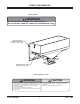
MOUNTING THE SPREADER Fixed Mount Spreader NOTE: The spreader shall be installed according to instructions supplied. Your local outlet is trained to provide this service and service your spreader with factory original parts. 1. Install the left and right top brackets to the truck bed rail with one 1/2" cap screw, one 1/2" flat washer and one 1/2" locknut. Attach the other hole in the top bracket to the bed rail with one 1/2" cap screw and one 1/2" locknut. WARN ING CAUT ION 2.
MOUNTING THE SPREADER 1. Fasten the left and right top brackets along with any shims to the truck bed rail with two 1/2" cap screws, two 1/2" flat washers and two 1/2" locknuts per bracket. Install the two 5/16" cap screws and locknuts to the side of the top brackets. SWING AWAY® Spreader 2. Place the left and right base plates on the bumper of the truck and line up with the holes in the bumper. CAU TION ER SPREAD SWING HOPPER THE DO NOT AL IN MATERI WITH 3.
OPERATING THE SPREADER Driving and Spreading on Snow and Ice Accessory Circuit The yellow wire in the vehicle harness is provided for accessory use of 12 amps or less. CAUTION Drinking and then driving or spreading is very dangerous. Your reflex, perceptions, attentiveness and judgement can be affected by even a small amount of alcohol. You can have a serious or even fatal collision if you drive after drinking. Please do not drink then drive or spread ice control materials.
OPERATING THE SPREADER Spreader Control Starting and Stopping the Motor There are two control options. They are the ON/OFF Control and the Variable Speed (PWM) Control. WARNING Before starting the spreader, the driver shall verify all bystanders are a minimum of 25 feet away from operating spreader. CAUTION If the unit is equipped with a SWING AWAY® mount. Do not operate the spreader or the vehicle without securing the hinge pin in the base plate. 1.
OPERATING THE SPREADER ON/OFF Control (Late Style) Stopping the Motor 1. Set the power switch to the OFF position to stop the motor. The power switch will remain in this position. The power switch OFF position operates as emergency stop when required. ON OFF BLAST NOTE: Always place the cover on the hopper to prevent moisture buildup. Do not let the spreader sit idle with material in the hopper for an extended period of time.
OPERATING THE SPREADER Variable Speed (PWM) Control Stopping the Motor with Variable Speed (PWM) Control 5 4 7 3 8 2 START BLAST 1. Set the power switch to the OFF position to stop the motor. The power switch will remain in this position. This is also the emergency stop position. 6 NOTE: Always place the cover on the hopper to prevent moisture buildup. Do not let the spreader sit idle with material in the hopper for an extended period of time.
REMOVING THE SPREADER NOTE: Empty the hopper before removing the spreader. CAUTION During removal or mounting, securely grip spreader to avoid dropping. Removing the SWING AWAY® Spreader NOTE: Empty the hopper before removing the spreader. 1. Unplug the spreader and stoplight (if equipped). 2. Remove the hitch pin from the latch side hinge pin. Removing the Fixed Mount Spreader 3. Remove the 1/4" cap screw and locknut from the hinged side hinge pin. 1. Unplug the spreader and stoplight (if equipped).
MAINTENANCE 4. If bearings pass inspection be sure to thoroughly grease them with a good quality multi-purpose grease. See Bearing Maintenance in this section. CAUTION Disconnect electric power at spreader electrical wiring harness connection and tag out if required before servicing or performing maintenance. 5. Verify all drive sprocket set screws are tight. Verify that all other fasteners are tight. Refer to the Torque Chart in the safety section of this manual. Cleaning 6.
MAINTENANCE Drive Belt Replacement Recycle Disconnect the electrical plug between the spreader and truck before drive belt replacement. When your spreader has performed its useful life, the majority of its components can be recycled as steel. Gear oil shall be disposed of according to local regulations. Balance of parts made of plastic shall be disposed of in customary manner. CAUTION Overtightening the belt may result in damage to the motor or bearings. 1. Remove the motor cap assembly. 2.
MAINTENANCE Bearing and Set Screw Maintenance Disconnect the electrical plug between the spreader and the truck before performing any maintenance. 1. Tighten all set screws shown after every 60 hours of use. 2. Grease the top and bottom drive shaft bearings as shown. Due to the harsh environment of the bottom bearing it will require more care than the top bearing. Top Bearing Set Screw Motor Pulley Set Screw Shaft Pulley Set Screw Top Bearing: Grease after every 60 hours of use.
4 PIN HARNESS WIRING DIAGRAM Cab Control White Connector Two-Way Molded Connector 6 Amp Fuse Red Connector 14 Ga. Red 8 Ga. Red To Vehicle Ignition (Accessory Wire or Fuse Box) 8 Ga. Red 30 Amp Fuse 14 Ga. Black _ Battery + 10 Ga. Red 8 Ga. Black 14 Ga. Yellow 14 Ga. Orange To Vehicle CHMSL Signal Accessory Circuit (12 AMP MAX) Vehicle Wiring Harness Spreader Wiring Harness Motor CHMSL Assy B A 14 Ga. Black 8 Ga. Red 14 Ga. Yellow Accessory Circuit 8 Ga. Black 14 Ga.
2 PIN HARNESS WIRING DIAGRAM Early Style (No Adapter Required) Late Style (Adapter Required) Speed Control To CHMSL Signal Speed Control Black Red White Black Black White Adaptor Black Fuse holder Red White Stoplight Vehicle Harness Fuse Butt Connector White + Black Battery Red Power Lead Battery Harness Vehicle Harness _ Black Vehicle Side Spreader Side Wiring Harness Wiring Harness CHMSL Motor Specification: 12V DC (0.
TROUBLESHOOTING Some of the solutions on the following page are complicated. If you are not properly trained or experienced in electrical or mechanical repairs, take you spreader to your local outlet for repairs. ON/OFF Control PROBLEM Ice control material not flowing POSSIBLE CAUSE 1. Bridging of material in hopper. 1. Control connector plug is loose. 2. Blown fuse. No power to cab control (Switch is in ON position indicator light not lit) 3. Low battery or loose connection. 4.
TROUBLESHOOTING Mechanical Problems - Variable Speed (PWM) and ON/OFF Control PROBLEM Ice control material not flowing POSSIBLE CAUSE 1. Bridging of material in hopper. 1. Drive belt is loose or damaged. 2. Motor pulley not secured to motor shaft. Spinner does not turn (Spreader motor is running) 3. Spinner pulley is not secured to the spinner shaft. 4. Spinner shaft bearings are dry or seized. 1. Drive belt is loose or damaged. 2. Pulley is not secured to the spinner shaft. 3.
TROUBLESHOOTING Early Production - 2 Pin Harness PROBLEM Ice control material not flowing POSSIBLE CAUSE Bridging of material in hopper Spreader Control power switch is in the OFF position Spreader Control circuit breaker is tripped (ON/OFF control only) Spinner does not spin – No power to the spreader control Battery lead in-line fuse is blown Battery connection is poor Battery wiring harness is damaged Spinner, auger, or driveshaft is jammed or overloaded Spinner shaft bearings are damaged Spinner d
FISHER ENGINEERING P.O. BOX 529 ROCKLAND, MAINE 04841 A DIVISION OF DOUGLAS DYNAMICS, L.L.C. Copyright © 2005 Douglas Dynamics, L.L.C. All rights reserved. This material may not be reproduced or copied, in whole or in part, in any printed, mechanical, electronic, film or other distribution and storage media, without the written consent of Fisher Engineering. Authorization to photocopy items for internal or personal use by Fisher Engineering outlets or spreader owner is granted.