
Weather Radio User Manual

Rosemount Models 244EH and 244ER PC-Programmable Temperature Transmitters
2-6
Head Mount Transmitter with Threaded Sensor
The least complicated assembly uses:
• a threaded sensor with flying leads
• the universal connection head
• a union and nipple extension assembly
•a threaded thermowell
Refer to Volume 1 of the Rosemount Sensors Product Data Sheet
(document number 00813-0100-2654) for complete sensor and
mounting accessory information.
To complete the assembly, follow the steps as described below.
1. Attach the thermowell to the pipe or process container wall. Install
and tighten thermowells before applying pressure.
2. Attach necessary extension nipples and adapters. Seal the nipple
and adapter threads with silicone tape.
3. Screw the sensor into the thermowell. Install drain seals if
required for severe environments or to satisfy code requirements.
4. Set the transmitter failure mode switch
(see Figure 2-13 on page 2-16).
5. Pull the sensor wiring leads through the extensions and adapters
into the universal head. Mount the transmitter in the universal
head by threading the transmitter mounting screws into the
universal head mounting holes.
6. Mount the assembly into the thermowell. Seal adapter threads
with silicone tape.
7. Install conduit for field wiring to the conduit entry of the universal
head. Seal conduit threads with silicone tape.
8. Pull the field wiring leads through the conduit into the universal
head. Attach the sensor and power leads to the transmitter. Avoid
contact with leads and terminals.
9. Install and tighten the universal head cover. Enclosure covers
must be fully engaged to meet explosion-proof requirements.
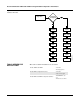
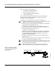
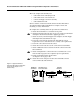
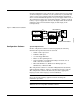
Figure 2-6. Typical Model 244EH
Transmitter Mounting Configuration
Using Threaded Style Sensor
and Assembly
644-0000A04A
Standard
Extension
Threaded Thermowell
Universal Head
Threaded Style Sensor