
Weather Radio User Manual


2-13
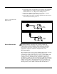
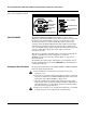
Use the following steps to wire the transmitter:
1. Connect the positive lead from the power supply to the transmitter
terminal marked “+” and the negative lead to the transmitter
terminal marked “–” (see Figure 2-11 and Figure 2-13).
2. Tighten the terminal compression screws to ensure adequate
contact. No additional power wiring is required.
3. After making connections, recheck the polarity and correctness of
connections, then turn the power on.
Figure 2-11. Transmitter Field
Wiring Diagrams
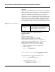
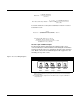
Sensor Connections The Models 244E are compatible with a number of RTD and
thermocouple sensor types. Figure 2-12 shows the correct input
connections to the sensor terminals on the transmitter. To ensure
proper sensor connections, anchor the sensor lead wires into the
appropriate compression terminals and tighten the screws.
RTD or Ohm Inputs
The transmitters will accept a variety of RTD configurations, including
2-wire, 3-wire, 4-wire, and compensation loop designs. If the
transmitter is mounted remotely from a 3-wire or 4-wire RTD, it will
operate within specifications, without recalibration, for lead wire
resistances of up to 10 ohms per lead (equivalent to 1,000 feet of
20 AWG wire). In this case, the leads between the RTD and transmitter
should be shielded. If using only two leads, both RTD leads are in series
with the sensor element, so significant errors can occur if the lead
lengths exceed three feet of 20 AWG wire (approximately 0.05 °C/ft).
For longer runs, attach a third or fourth lead as described above.
Model 244EH
Model 244ER
Note: Signal loop may be grounded at any point or left ungrounded.
Power
Supply
244-0000A02C
Power
Supply
644-0000A02D