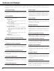
Table of Contents Table of Contents 2 To the Owner 3 Safety Instructions 4 Installing the Projector in Proper Position Air Circulation Moving the Projector 5 5 5 Compliance 6 Connecting the AC Power Cord 7 Features and Design 8 Part Names and Functions 9 Computer Input 24 Input Source Selection Computer System Selection Computer Adjustment (Auto) Computer Adjustment (Manual) Image Level Selection Image Level Adjustment Screen Size Adjustment 24 25 26 27 29 30 31 Video Input 32 Input So
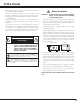
To the Owner Before operating this projector, read this manual thoroughly and operate the projector properly. This projector provides many convenient features and functions. Operating the projector properly enables you to manage those features and maintains it in better condition for a considerable time. Improper operation may result in not only shortening the product-life, but also malfunctions, fire hazard, or other accidents.
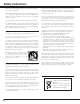
Safety Instructions All the safety and operating instructions should be read before the product is operated. Read all of the instructions given here and retain them for later use. Unplug this projector from AC power supply before cleaning. Do not use liquid or aerosol cleaners. Use a damp cloth for cleaning. This projector should be operated only from the type of power source indicated on the marking label.
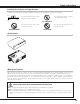
Safety Instructions Installing the Projector in Proper Position Install the projector properly. Improper installation may reduce the lamp lifetime and cause a fire hazard. 20˚ Do not put the projector on either side to project an image. Do not tilt the projector more than 20 degrees above and below. 20˚ NO SIDEWAYS Do not point the projector down to project an image. NO DOWNWARD Do not point the projector up to project an image.
Compliance Federal Communication Commission Notice Note : This equipment has been tested and found to comply with the limits for a Class B digital device, pursuant to part 15 of the FCC Rules. These limits are designed to provide reasonable protection against harmful interference in a residential installation. This equipment generates, uses and can radiate radio frequency energy and, if not installed and used in accordance with the instructions, may cause harmful interference to radio communications.
Compliance Connecting the AC Power Cord This projector uses nominal input voltages of 100-120 V or 200-240 V AC. This projector automatically selects the correct input voltage. It is designed to work with single-phase power systems having a grounded neutral conductor. To reduce risk of electrical shock, do not plug into any other type of power system. Consult your authorized dealer or service station if you are not sure of the type of power being supplied.
Features and Design This Multimedia Projector is designed with the most advanced technology for portability, durability, and ease of use. This projector utilizes built-in multimedia features, a palette of 16.77 million colors, and matrix liquid crystal display (LCD) technology. ◆ Compact Design This projector is extremely compact in size and weight. It is designed to be carried and work anywhere you wish to use.
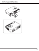
Part Names and Functions 9
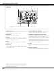
Part Names and Functions Terminal q w t AUDIO IN R L (MONO) VIDEO COMPUTER IN 1 DVI - I * r e S-VIDEO SERVICE PORT y USB COMPUTER / COMPONENT RESET AUDIO IN AUDIO OUT MCI COMPUTER IN 2 / COMPONENT IN / MONITOR OUT Do not press this button. This button is used for optional accessories. u i o q COMPUTER IN 1 DVI-I Connect computer output (Digital/Analog DVI-I type) or Multi Card Imager (optional) to this terminal.
Part Names and Functions Top This projector has control buttons and indicators on its top. q w e r t y ON - OFF POWER INPUT SELECT UME + VOL KEYSTONE UM VOL E – WARNING LAMP REPLACE MENU u q KEYSTONE button Corrects keystone distortion. (p20, 38) w INPUT button Selects input source. (p24, 32 ) e POWER ON–OFF button Turns the projector on or off. (p19) r SELECT button Executes the item selected. It is also used to expand / compress the image in Digital zoom +/– mode.
Part Names and Functions 12
Part Names and Functions Pointer Function You can move Spotlight or Pointer of the projector with the remote control to emphasize a part of the projected image. (See “Pointer” on page 40 for changing the patterns and sizes.) 1 While pressing the MENU button, hold down the NO SHOW button for more than 7 seconds so that the Pointer function can be available. (The Laser pointer function has switched to the Pointer function.
Part Names and Functions Remote Control Code This projector has eight different remote control codes (Code 1-Code 8); the factory-set, initial code (Code 1) and the other seven codes (Code 2 to Code 8). This switching function prevents remote control interference when operating several projectors or video equipment at the same time. (Change the remote control code for the projector first before changing that for the remote control. See “Remote control” on page 40.
Part Names and Functions 1 Remove the battery compartment lid. Press the lid downward and slide it. 2 Slide the batteries into the compartment. 3 Replace the compartment lid. Two AA size batteries For correct polarity (+ and –), be sure battery terminals are in contact with pins in compartment. To insure safe operation, please observe the following precautions : ● Use (2) AA, UM3 or R06 type alkaline batteries. ● Replace two batteries at the same time. ● Do not use a new battery with a used battery.
Installation Positioning the Projector This projector is designed to project on a flat projection surface and can be focused from 3.3’(1.0m) - 25.3’(7.7m). Refer to the figure and the table below for the screen size and the distance between the projector and the screen. A:B = 9:1 25.3' (7.7m) 300” (Inch Diagonal) 16.4' (5.0m) 12.5' (3.8m) 195” 195” 8.2' (2.5m) 150” 3.3' (1.0m) Min. Zoom 127” 100” 40” Max.
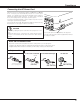
Installation Connecting to a Computer Cables used for connection (✽ = These accessories are not supplied with this projector.) • VGA Cable (HDB 15 pin) ✽ • DVI-VGA Cable (HDB 15 pin) • DVI-Digital Cable (for Single Link T.M.D.S.
Installation Connecting to Video Equipment Cables used for connection (✽ = These accessories are not supplied with this projector.) • Scart-VGA Cable ✽ • Component-VGA Cable ✽ • Video Cable (RCA x 1) ✽ • S-VIDEO Cable ✽ • Audio Cables (Mini Plug (stereo) x 2 or RCA x 2) ✽ Video Source (example) RGB Scart 21-pin Output Scart-VGA Cable ✽ Component Video Output (Y, Pb/Cb, Pr/Cr) ComponentVGA Cable ✽ COMPUTER IN 2 / COMPONENT IN/ MONITOR OUT Component video output equipment.
Basic Operation Turning On the Projector 1 Complete peripheral connections (with a computer, VCR, etc.) before turning on the projector. 2 Connect the projector's AC power cord into an AC outlet. The POWER indicator flashes red in a moment and turns on red. 3 Press the POWER ON-OFF button on the top control or on the remote control. The POWER indicator turns green, and the cooling fans start to operate. The preparation display appears on the screen and the count down starts.
Basic Operation Zoom Adjustment Move the Zoom Lever to zoom in and out. Zoom Lever Focus Adjustment Rotate the Focus Ring to adjust the projected picture focus. Focus Ring Keystone Adjustment If a projected picture has keystone distortion, correct the image with KEYSTONE adjustment. 1 Press the KEYSTONE button on the remote control or select Keystone in the Setting Menu (p38). The keystone dialog box appears. 2 Correct keystone distortion by pressing the Point Up/Down/Left/Right button.
Basic Operation No Show Function Press the NO SHOW button on the remote control to black out the image. To restore to normal, press the NO SHOW button again or press any other button. When a projected image is captured and set as “User” in the Logo item in the Setting Menu (p38), the screen changes each time you press the NO SHOW button as follows. black out ➜ the captured image ➜ normal ➜ • • • • • The message disappears after 4 seconds. P-Timer Function Press the P-TIMER button on the remote control.
Basic Operation You can control and adjust this projector through the On-Screen Menu. Refer to the following pages to operate each adjustment on the On-Screen Menu. 1 Press the MENU button to display the On-Screen Menu (Menu bar). A red frame is a pointer. 2 Move the pointer (red frame) to the Menu icon that you want to select by pressing the Point Left/Right button.
Basic Operation Menu Bar For computer source Guide Window PC System Menu Image Select Menu Screen Menu Setting Menu Shows the selected Menu of the OnScreen Menu. Used to select computer system. (p25) Used to select an image level among Standard, Real, and Image 1 ~ 4. (p29) Used to adjust size of image. [Normal / True / Wide / Digital zoom +/–] (p31) Used to change settings of the projector or reset lamp replace counter.
Computer Input Input Source Selection Direct Operation Choose either Computer 1 or Computer 2 by pressing the INPUT button on the top control or press the COMPUTER button on the remote control. Before using these buttons, correct input source should be selected through menu operation as described below. INPUT button Computer 1 ✽ Computer 2 Video COMPUTER button Computer 1 Computer 2 ✽ ✽ Computer 2 is not displayed when the COMPUTER IN 2/COMPONENT IN/MONITOR OUT terminal is used as Monitor out.
Computer Input Computer System Selection This projector can detect most of the current computer systems with the Multi-scan system and the Auto PC adjustment function provided in the projector. When selecting computer input, the projector automatically displays the most proper image for the input signal. One of the following four displays appears on the system menu icon.
Computer Input Computer Adjustment (Auto) Auto PC Adjustment function is provided to automatically adjust Fine sync, Total dots, Horizontal, and Vertical to conform to your computer. Auto PC Adjustment function can be operated as follows. 1 Press the MENU button and the On-Screen Menu will appear. Press the Point Left/Right button to move the red frame pointer to the PC Adjust Menu icon. 2 Press the Point Down button to move the red frame pointer to the Auto PC Adj.
Computer Input Computer Adjustment (Manual) Some computers employ special signal formats which may not be tuned by Multi-scan system of this projector. This projector has Manual PC Adjustment to enable you to precisely adjust several parameters to match those signal formats. The projector has 5 independent memory areas to memorize those parameters manually adjusted. This enables you to recall the setting for a specific computer whenever you use it.
Computer Input Display area Select the resolution at the Display area dialog box. Press the SELECT button at the Display area icon and the Display area dialog box appears. Display area H Adjusts the horizontal area displayed by this projector. Press the Point Left/Right button to decrease/increase value and then press the SELECT button. Display area Display area V Adjusts the vertical area displayed by this projector.
Computer Input Image Level Selection Direct Operation Select an image level among Standard, Real, Image 1, Image 2, Image 3, and Image 4 by pressing the IMAGE button on the remote control. IMAGE button Standard Real Standard Normal picture level preset on this projector. Image 1 Real Picture level with improved halftone for graphics. Image 2 IMAGE 1~4 User preset image in the Image Adjust Menu (p30). Image 3 Image 4 Menu Operation 1 Press the MENU button and the On-Screen Menu will appear.
Computer Input Image Level Adjustment 1 Press the MENU button and the On-Screen Menu will appear. Press the Point Left/Right button to move the red frame pointer to the Image Adjust Menu icon. 2 Press the Point Down button to move the red frame pointer to the item that you want to adjust, and then press the SELECT button. The level of each item is displayed. Adjust each level by pressing the Point Left/Right button.
Computer Input Screen Size Adjustment This projector has a picture screen resize function, which enables you to display the desirable image size. 1 Press the MENU button and the On-Screen Menu will appear. Press the Point Left/Right button to move the red frame pointer to the Screen Menu icon. 2 Press the Point Down button and move the red frame pointer to the function that you want to select and then press the SELECT button.
Video Input Input Source Selection (Video, S-Video) Direct Operation Choose Video by pressing the INPUT button on the top control or the VIDEO button on the remote control. Before using these buttons, correct input source should be selected through menu operation as described below. INPUT button Video Computer 1 Computer 2 ✽ VIDEO button Video ✽ When Monitor out is selected at the Terminal item in the Setting Menu, Computer 2 is not displayed.
Video Input Input Source Selection (Component, RGB Scart 21-Pin) Direct Operation Choose Computer 2 by pressing the INPUT button on the top control or press the COMPUTER button on the remote control. Before using these buttons, correct input source should be selected through menu operation as described below. INPUT button Computer 1 ✽ Computer 2 Video COMPUTER button Computer 1 Computer 2 ✽ ✽ Computer 2 is not displayed when the COMPUTER IN 2/COMPONENT IN/MONITOR OUT terminal is used as Monitor out.
Video Input Video System Selection 1 Press the MENU button and the On-Screen Menu will appear. Press the Point Left/Right button to move the red frame pointer to the AV System Menu icon. 2 Press the Point Down button to move the red arrow pointer to the system that you want to select and then press the SELECT button. Video or S-Video Auto The projector automatically detects incoming video system, and adjusts itself to optimize its performance.
Video Input Image Level Selection Direct Operation Select an image level among Standard, Cinema, Image 1, Image 2, Image 3, and Image 4 by pressing the IMAGE button on the remote control. IMAGE button Standard Cinema Standard Normal picture level preset on this projector. Image 1 Cinema Picture level adjusted for the picture with fine tone. Image 2 IMAGE 1~4 User preset image in the Image Adjust Menu (p36, 37).
Video Input Image Level Adjustment 1 Press the MENU button and the On-Screen Menu will appear. Press the Point Left/Right button to move the red frame pointer to the Image Adjust Menu icon. 2 Press the Point Down button to move the red frame pointer to the item that you want to adjust and then press the SELECT button. The level of each item is displayed. Adjust each level by pressing the Point Left/Right button.
Video Input Reset Resets all adjustment to their previous figure. Store To store the adjustment data, move the red frame pointer to the Store icon and press the SELECT button. The Image Level Menu will appear. Move the red frame pointer to the Image Level 1 to 4 and then press the SELECT button. Image Level Menu Move the red frame pointer to an image icon to be set and then press the SELECT button. Quit Closes the Image Adjust Menu.
Setting Setting 1 Press the MENU button and the On-Screen Menu will appear. Press the Point Left/Right button to move the red frame pointer to the Setting Menu icon. 2 Press the Point Down button to move the red frame pointer to the item that you want to set and then press the SELECT button. The Setting dialog box appears. Setting Menu (Language) Set the red frame pointer to the item and press the SELECT button.
Setting Ceiling Ceiling When this function is “On,” the picture is top/bottom and left/right reversed. This function is used to project the image from a ceiling mounting the projector. Rear When this function is “On,” the picture is left/right reversed. This function is used to project the image to a rear projection screen.
Setting Remote control This projector provides eight different remote control codes (Code 1Code 8); the factory-set, initial code (Code 1) and the other seven codes (Code 2 to Code 8). This switching function prevents remote control interference when operating several projectors or video equipment at the same time. For example operating the projector in “Code 7”, both the projector and the remote control must be switched to “Code 7”. To chanD 31 0 10 57.
Maintenance and Cleaning Warning Indicator The WARNING indicator shows the state of the function which protects the projector. Check the state of the WARNING indicator and the POWER indicator to take proper maintenance. The projector is shut down and the WARNING indicator is flashing red TOP CONTROL WARNING LECT NOTE ● After the temperature inside the projector returns to normal, the WARNING indicator still continues to flash. When the projector is turned on again, the WARNING indicator stops flashing.
Maintenance and Cleaning Follow these steps to clean the projection lens. 1 Disconnect the AC power cord before cleaning. 2 3 42 When the projector is not in use, replace the lens cover.
Maintenance and Cleaning Lamp Replacement When the life of the projection lamp of this projector draws to an end, the LAMP REPLACE indicator lights yellow. If this indicator lights yellow, replace the lamp with a new one promptly. Top Control POWER SELECT UME + VOL CAUTION UM VOL E – WARNING This indicator lights yellow when the life of the projection lamp draws to an end. LAMP REPLACE CAUTION Allow a projector to cool, for at least 45 minutes before you open the Lamp cover.
Maintenance and Cleaning Lamp Replace Counter Be sure to reset the lamp replace counter after the lamp is replaced. When the lamp replace counter is reset, the LAMP REPLACE indicator stops lighting. 1 Turn the projector on, press the MENU button and the OnScreen Menu will appear. Press the Point Left/Right button to move the red frame pointer to the Setting Menu icon. 2 Press the Point Down button to move the red frame pointer to the Lamp counter reset item and then press the SELECT button.
Appendix Troubleshooting Before calling your dealer or service center for assistance, check the items below once again. – Make sure you have properly connected the projector to peripheral equipment as described in "Connecting to a Computer" and “Connecting to Video Equipment” on page17 and 18. – Make sure all equipment is connected to AC outlet and the power is turned on. – When you operate the projector with a computer and it does not project an image, restart the computer.
Appendix Problem: – Try these solutions. Computer 2 cannot be selected. – Select Computer 2 at the Terminal item in the Setting Menu. (See “Terminal” on page 39.) The Terminal item cannot be selected. – The Terminal item in the Setting Menu cannot be selected after Computer 2 is selected. Select other input source such as Computer 1 or Video with the INPUT button on the top control, the COMPUTER button or the VIDEO button on the remote control so that the Terminal item can be selected.
Appendix Check the indicators for projector condition. • • • lights green. • • • flashes green. • • • lights red.
Appendix Menu Tree Computer Input / Video Input Input Computer 1 RGB( Analog ) Go to System (1) RGB( PC Digital ) N/A RGB( AV HDCP ) N/A RGB Go to System (1) Component Go to System (2) Computer 2 Video RGB( Scart ) N/A Auto Go to System (3) Video Go to System (3) S-Video Go to System (3) ✽N/A - - - not applicable Computer Input System (1) MODE 1 MODE 2 SVGA 1 ---- Image Select Standard Real Image 1 Image 2 Image 3 Image 4 Image Adjust Contrast Brightness Color Temp 0 - 63 0 - 63
Appendix Setting Video Input System (2) Auto 1080i 1035i 720p 575p 480p 575i 480i System (3) Image Select Image Adjust Volume Mute Quit 0 - 63 On / Off Setting Language English German French Italian Spanish Portuguese Dutch Swedish Russian Chinese Korean Japanese Quit Keystone Blue back Display Store / Reset On / Off On / Off Logo Standby mode Off User Default Yes/No On / Off On / Off Computer 2 Monitor out Eco/Normal Power management Off Auto PAL SECAM NTSC NTSC 4.
Appendix Compatible Computer Specifications PLC-XU55/PLC-XU50 can basically accept the signal from all computers with the V, H-Frequency mentioned below and less than 140 MHz of Dot Clock. PLC-SU50 can basically accept the signal from all computers with the V, H-Frequency mentioned below and less than 100 MHz of Dot Clock. These modes are not available on PLC-SU50.
Appendix Technical Specifications Model No.
Appendix Configurations of Terminals COMPUTER INPUT/COMPONENT INPUT/MONITOR OUTPUT TERMINAL (ANALOG) Terminal : HDB15-PIN Pin Configuration 4 5 10 15 14 2 3 9 8 13 1 7 12 1 2 3 4 5 6 7 8 6 11 Red Input Green Input Blue Input Sense 2 Ground (Horiz.sync.) Ground (Red) Ground (Green) Ground (Blue) 9 10 11 12 13 14 15 +5V Power Ground (Vert.sync.) Sense 0 DDC Data Horiz. sync. Vert. sync.
Appendix SERVICE PORT CONNECTOR Terminal : Mini DIN 8-PIN Pin Configuration 8 5 7 6 4 3 2 1 1 2 3 4 5 6 7 8 PS/2 ----CLK DATA GND --------GND ----- 1 2 3 4 Vcc - Data + Data Ground Serial RXD --------GND RTS / CTS TXD GND GND ADB ----ADB ----GND ------------GND USB CONNECTOR (Series B) Pin Configuration 2 1 3 4 Optional Parts The parts listed below are optionally supplied. When ordering those parts, give the name and Type No. to the sales dealer. ● MAC Adapter Type No.
Appendix Attaching the Lens Cover 54
Printed in Japan Part No. 610 308 4688 (1AA6P1P4129-- MT3A) SANYO Electric Co., Ltd.