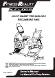
410 ST SMART TECHNOLOGY RECUMBENT BIKE IMPORTANT: Read all instructions carefully before using this product. Retain this owner’s manual for future reference. The specifications of this product may vary from this photo, subject to change without notice. 2161.
PLEASE DO NOT RETURN THIS PRODUCT TO THE STORE. STOP. Contact customer service if you have any questions regarding assembly or proper operation of the machine. Email us at: Service@paradigmhw.
TABLE OF CONTENT SERVICE ------------------------------------------------------------------------ 2 LABEL PLACEMENT --------------------------------------------------------- 3 IMPORTANT SAFETY GUIDELINES ------------------------------------- 4 OVERVIEW DRAWING ---------------------------------------------------- 6 PART LIST --------------------------------------------------------------------- 7 HARDWARE & TOOLS PACK -------------------------------------------- 9 ASSEMBLY -----------------------
SERVICE IMPORTANT: FOR NORTH AMERICA ONLY For damaged or defective product, questions, replacement parts or any other service support, please contact our customer service department by the below methods: For The Best Service, please Email: service@paradigmhw.com Response Time: 1-2 Business Days Emailing us with the information above will be the best method to receive a response during peak business hours Website: www.paradigmhw.
LABEL PLACEMENT 3
IMPORTANT SAFETY GUIDELINES Read all instructions before using the equipment. When using the equipment, basic precautions should always be followed. WARNING - To reduce the risk of injury to persons, read and under the following: 1. Make sure your equipment is correctly assembled before you use it. 2. Be sure all screws, nuts, and bolts are tightened prior to use. 3. Before using this equipment, we recommend doing warm ups and stretching of the major muscle 4. 5. groups.
IMPORTANT SAFETY GUIDELINES Do not use this equipment if you have any of the following conditions or ailments: • • • • • • • • • • Pregnancy Extreme obesity Middle ear infection Hiatus hernia or Ventral hernia Glaucoma, retinal detachment or conjunctivitis Use of anticoagulants including Aspirin in high doses.
OVERVIEW DRAWING 6
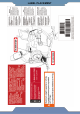
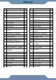
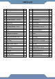
PARTS LIST No. Description Q’ty No. Description Q’ty 1 Main Frame 1 30 Left Pedal Strap 1 2 Front Post 1 31 Rear Right Cover 1 3 Seat Sliding Tube 1 32 Rear Left Cover 1 4 Right Handrail Support Tube 1 33 Arm Rest 2 5 Left Handrail Support Tube 1 34 Big Curved Washer Ф6*Ф16*1.
PARTS LIST No. Description Q’ty No. 59 Crank Cap 2 86 Hex Bolt M6*15 2 60 Left Crank 1 87 Spring 1 2 88 Hex Nut M6 2 62 Crank Cover 2 89 Adjustable Rod 1 63 Screw ST4.2*20 14 90 Brake Adjustment 1 64 Self-Drilling Screw ST4.2*20 19 91 Hex Bolt M6*15 2 65 Right Cover 1 92 Plastic Bushing 2 66 Bearing Cup 2 93 Link Stopper 1 67 Ball Bearing 2 94 Brake Cover 1 68 Self-Drilling Screw ST2.
HARDWARE & TOOL PACK 9
ASSEMBLY Tools: 6mm Allen Wrench 1PC Discard (B) Discard (A) Step 1 1a. Remove the Metal Tubes from the Main Frame (1) by using 6mm Allen Wrench provided. 1b. Discard the metal tubes A and B and the associated hardware at that was removed. These parts are not needed for the assembly of the bike.
ASSEMBLY Tool: Multi Hex Tool with Phillips Screwdriver 1PC Step 2 2a. Front Stabilizer Installation – Lift up the front of the Main Frame (1), and attach the Front Stabilizer (10) onto the front curve of the Main Frame (1) with two Carriage Bolts (23), two Curve Washers (22), two Spring Washers (15), and two Cap Nuts (21). Use the Multi Hex Tool with Phillips Screwdriver to tighten the Cap Nuts (21) until they are firm and secure. 2b.
ASSEMBLY Tool: Multi Hex Tool with Phillips Screwdriver 1PC Step 3 3a. Installing the Left & Right Pedal Straps to the Pedals: Install the Left Pedal Strap (30) onto the Left Pedal (29). Install the Right Pedal Strap (28) onto the Right Pedal (27). See Figure A. 3b. Installing the Left Pedal: Insert the threaded shaft of the Left Pedal (29) into the threaded hole on the Left Crank (60). Turn the pedal shaft by hand in a counter-clockwise direction until snug.
ASSEMBLY Tool: 6mm Allen Wrench 1PC Step 4 4a. Removal of Hardware for Installation: Remove four Flat Washers (16), seven Hex Bolts (14), seven Spring Washers (15) and three Curved Washers (17) from the Main Frame (1). 4b. Connecting the Pulse and Console Wires: Connect the Console Wire (12) from the Front Post (2) to the Lower Console Wire (19) from the Main Frame (1). Connect the Hand Pulse Wire (13) from the Front Post (2) to the Lower Hand Pulse Wire (20) from the Main Frame (1). See Figure B. 4c.
ASSEMBLY Tool: Multi Hex Tool with Phillips Screwdriver 1PC Step 5 5a. Left & Right Cup Holder Installation: Attach the Left and Right Cup Holder (18) & (48) onto the Front Post (2) with two Self-Drilling Screws (64) using the Multi Hex Tool with Phillips Screwdriver provided.. 5b. Align the edges of the Left and Right Cup Holder (18) & (48). 5c. Secure the Left and Right Cup Holder (18) & (48) together with three Self-Tapping Screws (108) using the Multi Hex Tool with Phillips Screwdriver provided.
ASSEMBLY Tools: 6mm Allen Wrench 1PC 5mm Allen Wrench 1PC Step 6 6a. Removal of Hardware for Installation: Remove four Hex Bolts (38), four Spring Washers (15) and four Flat Washers (16) from the Main Frame (1). 6b. Installing the Seat Slide Tube: Attach the Seat Slide Tube (3) onto the Main Frame (1) by aligning the four holes on the Seat Slide Tube (3) and the Main Frame (1) using the previously removed four Hex Bolts (38), four Flat Washers (16), and four Spring Washers (15).
ASSEMBLY Tool: Multi Hex Tool with Phillips Screwdriver 1PC 3 Step 7 7a. Installing the Left and Right Front Cover: Attach the Left Front Cover (25) and Right Front Cover (26) onto the Seat Slide Tube (3) with two Self-Drilling Screws (64). Align the edges of the covers and use one Screw (63) to secure both covers together. Tighten the hardware using the Multi Hex Tool with Phillips Screwdriver provided. 7b.
ASSEMBLY Step 8 8a. Removing Hardware for Installation: Remove four Socket Phillips Screws (36) from the Seat Post (8). 8b. Handrail Support Tube Installation: Attach the both Right and Left Handrail Support Tubes (4) & (5) onto the Seat Post (8) with the four Socket Phillips Screws (36). Tighten all the Screws (36) with the Multi Hex Tool with Phillips Screwdriver provided. Tools: Pre-Installed Hardware: Multi Hex Tool with Phillips (36) Socket Phillip Screw Screwdriver 4PCS 1PC Step 9 9a.
ASSEMBLY Tools: 5mm Allen Wrench 1PC 6mm Allen Wrench 1PC Multi Hex Tool with Phillips Screwdriver S10, S13, S14, S15 1PC Step 10 10a. Installing the Left Handlebar and Backrest: Align the holes of the Backrest (44) and Left Handlebar (7) to the holes of the Seat Post (8). Secure the Backrest (44) and Left Handlebar (7) with four Hex Bolts (42), four Spring Washers (54) and four Flat Washers (43). Tighten the Hex Bolts (42) using the 5mm Allen Wrench provided. 10b.
ASSEMBLY 4 5 Tool: 6mm Allen Wrench 1PC Step 11 11a. Installing the Arm Rests: Attach both Arm Rest (33) to the Right/Left Handlebars (6) & (7) and Right/Left Handrail Support Tubes (4) & (5) with four Hex Bolts (35) and four Big Curved Washers (34). Tighten the Hex Bolts (35) using the 6mm Allen Wrench provided.
ASSEMBLY Tool: Multi Hex Tool with Phillips Screwdriver 1PC Step 12 12a. Removal of Hardware for Installation: Remove the four Phillips Screws (107) from the back of the Console (11). 12b. Connecting the Console Wires: Connect the Console Wire (12A) from the Front Post (2) to the Upper Console Wire (12B) from the Console (11). Connect the Hand Pulse Wire (13A) from the Front Post (2) to the Upper Hand Pulse Wires (13B) from the Console (11). See Figure C. 12c.
ASSEMBLY Step 13 13. Installing the Power Adaptor: Plug the small end of the Adaptor (24) into the Adaptor Wire (103) located on the front of the Right Cover (65).
CONSOLE 1. Button Functions START: 1. Begins the desired workout. 2. Resumes a paused workout session. STOP: 1. While exercising, press to pause a workout. 2. While paused, press to end the workout. 3. Press and hold for 3 seconds to reset the console. RETURN: 1. Return to the previous screen. UP ARROW: 1. While setting up a workout, press to navigate through the options. 2. While setting up a workout, press to increase a value when prompted. 3. While exercising, press to increase the workout resistance.
CONSOLE GENERAL FUNCTIONS: Use the UP or DOWN buttons to navigate the console options: PROGRAMS, and USERS then press OK to continue through each of the function's options. QUICK START: When the console first turns on you can enter a QUICK START work out by immediately pushing the START button at the main screen. PROGRAM: Preset Program 1. At the main screen use the UP or DOWN buttons to navigate to the “PROGRAMS” selection, then press OK. 2. Select “PROGRAMS”, and then press OK to confirm the selection.
CONSOLE CUSTOM: Customized Programs 1. At the main screen use the UP or DOWN buttons to navigate to the “PROGRAMS” selection, then press OK. 2. Use the UP or DOWN buttons to navigate to “CUSTOM”, then press OK to confirm the selection. 3. Press the UP or DOWN buttons to select between C1 or C2, then Press OK. Custom mode allows the user to create a preset workout profile. 1. Use the UP or DOWN buttons to change the resistance of each column, Press OK to confirm the selection and move to the next.
CONSOLE Users: User Selection 1. At the main screen use the UP or DOWN buttons to navigate to the “USERS” selection, then press OK. 2. Use the UP or DOWN buttons to navigate to between User1 through User4 and press OK. 3. Use the UP or DOWN buttons to navigate to between the PROGRAM or EDIT USER functions and press OK. a. PROGRAMS: Will take you to the menu choices to set up a workout using the selected user data. b.
ADJUSTMENTS Adjusting the Seat Forward or Back 1. To adjust the seat to your height, move the Adjustable Rod (89) forward to release the Seat Post (8). 2. Adjust the seat to a comfortable position and then move the Adjustable Rod (89) back to lock the Seat Post (8) into place. 1 47 72 47 9 Adjusting the Stability of the Bike 1. Turn the Adjustable Pads (47) on the Rear Stabilizer (9) as needed to level the recumbent bike. 2.
TROUBLESHOOTING & MAINTENANCE TROUBLE SHOOTING 1. PROBLEM: The recumbent bike wobbles when in use. 1) SOLUTION: Turn the Adjustable Pads (47) on the Rear Stabilizer (9) or the Adjustable Leveler (72) on the bottom of the Main Frame (1) as needed to level the recumbent bike. 2. PROBLEM: The display on the Console (11) does not turn on. 1) SOLUTION: Remove the Console (11) and verify that the wires from the Console (11) are properly connected to the wires of the Front Post (2).
TROUBLESHOOTING & MAINTENANCE Problem Potential Cause Correction E1 1. The motor does not activate Motor Problems Symptoms include an unusually loud noise coming from the Motor, which means the Gears are NOT meshing correctly. Try reversing the resistance and try again. If this fails then contact customer service. Problem Potential Cause Correction E2 1. There is something wrong with the cables. Check if the cables are damaged or not to cause circuit short. 2.
TRANSPORT & STORAGE Transporting the Bike Lift the Rear Stabilizer (9) with both hands until the Wheels of the Front Stabilizer (10) make contact with the ground. Pull or push the bike to the desired work out area or storage area. Gently lowering the bike after transporting, and always maintain both hands on the handle of the Rear Stabilizer (9) while transporting. Storage Store the bike in a clean and dry environment away from pets and children.
WARRANTY MANUFACTURER’S LIMITED WARRANTY Paradigm Health & Wellness warrants to the original purchaser that this product is free from defects in material and workmanship when used for the purpose intended, under the conditions that it has been installed and operated in accordance with Paradigm’s Owner’s Manual.
PARTS REQUEST FORM Paradigm Health & Wellness, Inc. EMAIL THIS FORM WITH YOUR RECEIPT OF PURCHASE TO Service@paradigmhw.