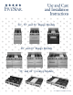
★ ★ ★ ★ ★ ★ ★ ★ ★ ★ ★ ★ ★ ★ ★ ★ ★ ★ ★ ★ ★ ★ ★ ★ ★ ★ ★ ★ ★ ★ ★ ★ ★ ★ ★ ★ ★ ★ ★ ★ ★ ★ ★ ★ ★ ★ ★ ★ ★ ★ ★ ★ ★ ★ ★ ★ ★ ★ ★ ★ ★ ★ ★ ★ ★ ★ ★ ★ ★ ★ ★ ★ ★ ★ ★ ★ ★ ★ ★ ★ ★ ★ ★ ★ ★ ★ ★ ★ ★ ★ ★ ★ ★ ★ ★ ★ ★ ★ ★ ★ Models ★36”★Range ★ and ★ 30” 24”, ★ ★ ★ ★ ★ ★ ★ ★ ★ ★ ★ ★ ★ ★ ★ ★ ★ ★ ★ ★ ★ ★ ★ ★ ★ ★ ★ ★ ★ ★ ★ ★ ★ ★ ★ ★ ★ ★ ★ ★ ★ ★ ★ ★ ★ ★ ★ ★ ★ ★ ★ Models ★ 60”★Range ★ and 48” ★ ★ ★ ★ ★ ★ ★ ★ ★ ★ ★ ★ ★ ★ ★ ★ ★ ★ ★ ★ ★ ★ ★ ★ ★ ★ ★ ★
INSTALLER: PLEASE LEAVE THIS MANUAL WITH THE RANGE FOR INSPECTION AND SERVICE USE. CONSUMER: PLEASE RETAIN THIS MANUAL FOR FUTURE REFERENCE. Before using your range or cooktop, read this book carefully. Record the model and serial numbers. • It is intended to help you operate and maintain your new range or cooktop properly. You’ll find them on a rating label under the cooking surfaces. Depending on the features of your range, the label may be under the griddle or on the side wall.
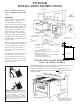
FIVESTAR INSTALLATION INSTRUCTIONS 40” MINIMUM Please read these instructions before attempting to install this range Unpacking Check the range carton for visible damage. If there is damage or even creases in the carton contact the carrier, request an inspection, and file the appropriate freight claim. Do not refuse shipment. Responsibility for shipping damage is with the carrier and the dealer or end user. Cut the shipping straps then carefully lift the carton up from the range.
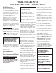
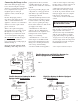
WALL CLEARANCES GAS AND ELECTRIC CONNECTIONS Wall Clearances All units must be installed in accordance with minimum side wall clearances and clearances extended vertically above the cooking top. See Figs. 1 & 6 for illustration. This unit may not be installed directly adjacent to sidewalls, tall cabinets, tall appliances, or other side vertical surfaces above the 36” cooking surface height.
Connecting the Range to Gas piping method is used, you must carefully align the pipe; the range cannot be moved after the connection is made. Shut off the main gas supply valve before disconnecting the old range and leave it off until new hook-up has been completed. Don’t forget to relight the pilot on other gas appliances when you turn the gas back on. To prevent gas leaks, put pipe joint compound on, or wrap pipe thread with Teflon* tape all around male (external) pipe threads.
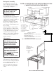
Backguard Assembly The backguard, located in the “top pack” of the range, must be installed prior to placing the range in position for gas hookup. See Figure 7. NOTE: COOKTOPS DO NOT HAVE LEVELING LEGS. CABINET SUPPORT MUST BE LEVEL. 40” MINIMUM NEVER BLOCK THE FLOW OF AIR FOR COMBUSTION OR VENTILATION. SEE INSTRUCTION FIG. 2. 13” MAXIMUM WIDTH OF RANGE Positioning/Leveling To position the range use a lift jack or enough manpower to lift the range completely.
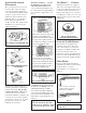
Oven/Griddle Control (Thermostat) The oven pilot gas selector screw is located on this control. To change oven pilot gas setting: (A) Remove oven control knob by pulling straight out. The oven gas selector screw is found in the lower left hand corner indicating “LP” or “N”. (B) These letters will appear upside down reading “N” and “LP”. (C) Rotate the adjustment screw tab to the proper setting. See Figure 8. Standard top burners . . . Be sure the shipping screws have been removed from the burners.
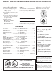
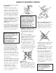
SAFETY INSTRUCTIONS • Read all instructions before using this appliance. Statistics show many accidents occur in the home. Most of these could be prevented with care and judgment. Use this appliance only for its intended use as described in this manual. When using appliances, basic safety precautions should be observed, including the following: • Be sure your appliance is properly installed and grounded by a qualified technician in accordance with the provided installation instructions.
• DO NOT TOUCH BURNERS, BURNER GRATES, OR INTERIOR SURFACE OF OVEN. These surfaces may be hot enough to burn even though they appear to be cool. During and immediately after use do not touch, or let clothing or other flammable materials contact any hot surfaces or any interior area of the oven; allow sufficient time for cooling. Potentially hot surfaces include the cooking surface and areas facing the cooking surface, oven vent opening and surfaces near the opening, and crevices around the oven door.
ENERGY-SAVING TIPS Surface Cooking MEDIUM–quick browning. Cook fresh vegetables with a minimum amount of water in a covered pan. LOW–finish cooking most quantities, double-boiler heat, and for small quantities. Watch foods when bringing them quickly to cooking temperatures at high heat. When food reaches cooking temperature, reduce heat immediately to lowest setting that will keep it cooking. VARI-FLAMETM FRONT BURNERS SIM–to maintain serving temperature of most foods.
of the electronic system. On sealed burner models, if equipped with flame sensing ignitors, the clicking sound stops after ignition. Each time a knob is placed in the “LITE” position all electrodes will spark. There are electrodes under the top for each pair of burners and one for the griddle. There is one electrode in each broiling section for the oven burner. In the event of a power failure you may light the top burners with a match.
Use of Oven • Preheat not more than ten to twelve minutes. • Allow at least one inch space around oven pans and the oven walls. Correct pan placement allows air circulation for proper baking and browning. • Do not place pans in the oven directly over each other. Stagger the pans so that air flow will not be inhibited. See Figure 14. • Always keep oven vent ducts unobstructed. set directly from “OFF” to the desired temperature and not turned back toward “OFF”. Imagine that the control has three sections: 1.
Oven Rack Removal To replace the oven rack, guide the angled rear portion of the rack under the rack keeper and slide the rack to the rear. position. Insert the pan and grill into the recessed section of the broiler rack making certain that the “pan keeper” pins clear the front edge of the broiler rack. Slide the pan and grill in place under the pan retainers. Push the pan and rack to the rear of the broiler compartment. Close the broiler door.
Electronic Ignition Ranges and built-in cooktops have top igniter electrodes. When a top burner knob is turned to the “LITE” position electrodes will spark at a rate of approximately 21/2 pulses (sparks) per second. On sealed burner models equipped with “flame sensing” the sparking will stop once the burner has ignited. On standard burner models, after ignition, rotate the knob slightly clockwise to stop sparking.
within the oven to escape without the forming of visible moisture on the range. The amount of moisture will depend upon the humidity of the air and water content of the food being cooked. Fogging and even dripping water will usually occur in geographic locations of high humidity. Oven Door Hinges The oven door hinges are properly set before leaving the factory.
Lift-Off Oven Door (on some models) LIFT OFF DOOR To remove oven door/s: • Open door fully. • Rotate the “hinge retainers” into the locked position, as shown over the hook located on the bottom side of each hinge quadrant. • Lift the door slightly, to clear “hinge slots”, and pull straight out to clear hinge mechanism from main front opening.
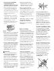
CONVECTION OVEN MODELS FAN HOUSING Convection oven ranges offer the choice of “regular” radiant baking and roasting or convection baking and roasting. The benefits of convection cooking are: BROIL ELEMENT CONVECTION FAN RACK POS. #4 RACK POS. #3 1. More even baking and roasting. RACK POS. #2 2. A general reduction in cooking time for most baked foods; up to 30% faster. RACK POS. #1 3. Or the opportunity to reduce cooking temperature and stay with original recipe cooking time.
Baking Chart Product and Type CAKE Yellow-2 layers White-2 layers Chocolate-2 layers Bundt Angel Food Pound Cake Snacking Cake Cupcakes Sheet Cake PIES Two Crust Fruit, fresh Fruit, frozen One Crust Custard, fresh Custard, frozen Pie Shell COOKIES Chocolate Chip Peanut Butter Sugar Brownies BREADS, YEAST Loaf Rolls BREADS, QUICK Loaf, Nut, Fruit Gingerbread Cornbread Cornbread Muffins Biscuits Muffins Pan Size Rack* Position Temp.
Convection Baking of Frozen Convenience Foods • Follow package recommendations for oven temperature, foil covering and use of cookie sheets. Baking times will be similar. See chart below for some examples. • Center foods in the oven. If more than one food item is being baked or if foods are being baked on multiple racks, stagger foods for proper air circulation. • Most foods are baked on rack position #3., see page 17. • For multiple rack baking, use rack # 2 and 4.
• The oven has a VARIABLE BROIL FEATURE which means that the broiling temperature can be varied by selecting a lower temperature setting on the TEMPERATURE knob. Using a lower temperature setting will cause the broil element to cycle on and off. This feature can be used for foods that need to cook more slowly or need less radiant heat. If foods are broiling too fast, the control can be set at a lower temperature to reduce the cooking speed rather than moving the broiler pan to a lower rack.
SELF-CLEANING INSTRUCTIONS Description – Self-cleaning ovens clean with high temperature (well above cooking temperatures) which eliminates soil completely or reduces it to a fine powdered ash for easy clean up with a damp cloth. WARNING - During the selfcleaning cycle, the exterior of the range can become very hot to the touch. DO NOT leave small children unattended near the appliance. CAUTION - DO NOT line the oven with aluminum foil.
MODEL NO. WARNING: Use caution when opening the door after the selfclean cycle. The oven may still be VERY HOT. CAUTION: We recommend you not use your range during the selfclean cycle. The range can become very hot to the touch. CAUTION: DO NOT force the door open before the oven has cooled sufficiently, the door lock could be damaged. To lock or unlock follow instructions. STARTING THE SELF-CLEAN CYCLE 22 1. Close the oven door. There is an interlock switch that senses when the door is fully closed.
MODEL NO.
WIRING DIAGRAM FOR GAS RANGES WITH ELECTRICAL EQUIPMENT TOP BURNER IGNITION SWITCHES TOP LEFT IGNITION LEFT T'STAT TOP CENTER IGNITION RIGHT T'STAT GRIDDLE IGNITION WIRING DIAGRAM FOR GAS RANGES WITH ELECTRICAL EQUIPMENT TOP LEFT IGNITION TOP RIGHT IGNITION GRIDDLE IGNITION TOP RIGHT IGNITION REIG 4 REIG 3 LEFT OVEN IGNITION REIG 4 REIG 3 REIG 2 REIG 1 GROUND LINE NEUTRAL REIG 4 REIG 3 GRIDDLE IGNITION REIG 2 REIG 1 RIGHT OVEN IGNITION RIGHT OVEN LAMP REIG 2 REIG 1 GRIDDLE IGNITION FAN
WIRING DIAGRAM FOR GAS RANGES WITH ELECTRICAL EQUIPMENT WIRING DIAGRAM FOR GAS RANGES WITH ELECTRICAL EQUIPMENT OVEN T'STAT TOP BURNER IGNITION SWITCHES GRIDDLE IGNITION SWITCH TOP BURNER IGNITION SWITCHES REIG 1 NEUTRAL REIG 1 REIG 2 GROUND REIG 1 LINE TOP RF IGNITION REIG 4 TOP CF IGNITION NEUTRAL TOP LF IGNITION REIG 4 REIG 3 REIG 3 REIG 2 REIG 4 REIG 3 REIG 2 REIG 1 GROUND LINE NEUTRAL REIG 4 REIG 3 REIG 2 REIG 1 TOP RR IGNITION REIG 2 GROUND REIG 1 LINE TOP CR IGNITION REIG 4 TOP
WIRING DIAGRAM FOR 60'' SELF CLEANER MODEL NO. 625 188-6C048 625 188-6C048 REV. 0 SEE RATING PLATE FOR TOTAL WATTAGE AND VOLTAGE USE ONLY COPPER OR ALUMINUM CONDUCTORS SEE INSTALLATION INSTRUCTIONS OR IF LOCAL CODES DO NOT PERMIT GROUNDING THROUGH THE NEUTRAL, DISCONNECT THE LINK FROM THE NEUTRAL AND USE GROUNDING TERMINAL OR LEAD TO GROUND UNIT IN ACCORDANCE WITH LOCAL CODES. CONNECT NEUTRAL TERMINAL OR LEAD TO BRANCH CIRCUIT NEUTRAL IN USUAL MANNER.
WIRING DIAGRAM FOR 48'' SELF CLEAN MODEL NO. 525 BLACK STRAIN RELIEF STANDARD 120/240V HOOKUP FRAME GROUNDED TO NEUTRAL THROUGH A LINK 188-6C049 WIRING RANGE CONNECTION CORD (FOR DUAL-FUEL RANGES ONLY) FIG. 1 FIG. 2 BLACK WHITE GROUND LINK WHITE RED RED WHITE BLACK RED GREEN STRAIN RELIEF STANDARD 120/240V HOOKUP WHERE SEPARATE GROUND IS REQUIRED ‘WARNING’ THIS APPLIANCE MUST BE CONNECTED AS SHOWN IN FIGURE 1, OR 2.
188-6C050 WIRING DIAGRAM FOR 36'' SEALED BURNER MODEL NO. 335, 337 188-6C051 335 188-6C051 REV. 0 OR IF LOCAL CODES DO NOT PERMIT GROUNDING THROUGH THE NEUTRAL, DISCONNECT THE LINK FROM THE NEUTRAL AND USE GROUNDING TERMINAL OR LEAD TO GROUND UNIT IN ACCORDANCE WITH LOCAL CODES. CONNECT NEUTRAL TERMINAL OR LEAD TO BRANCH CIRCUIT NEUTRAL IN USUAL MANNER. CONSULT MANUFACTURER’S INSTRUCTIONS WHEN CODES REQUIRE THAT 3-CONDUCTOR CORD ASSEMBLIES MUST BE REPLACED BY 4-CONDUCTOR CORD ASSEMBLIES.
PORTABLE FIVESTAR GRIDDLE FOR “STANDARD” BURNERS ONLY MODEL NO. FSG010 1) REMOVE GRATES 2) PLACE GRIDDLE OVER FRONT BURNER PAN LOCATOR. 10” x 21” GRIDDLE CAN BE USED OVER ANY TWO TOP BURNERS. FOR BEST RESULTS BOTH BURNERS SHOULD BE “ON” AT DESIRED SETTING. FITS OVER BURNER PAN LOCATOR CAUTION: ALWAYS REMOVE TOP BURNER GRATES TO AVOID DAMAGE WHILE USING GRIDDLE Griddle Cooking Griddle Clean Up • Preheat griddle at selected temperature for approximately 10 minutes.
FIVESTAR MODEL FSG011 GRILL INSTALLATION 1. Carefully set aside the burner grates and burner pans as needed, then remove the entire griddle module and set aside or store. 2. Position the grill frame assembly on the griddle/grill housing as shown. GRILL RACK 3. Remove the flame spreader and position both long drip pans. One on the extreme left and one on the extreme right being careful not to disturb wiring or tubing. *Note: Except for cleaning, the drip pans can remain in place during griddle operation.
FIVESTAR INSTALLATION INSTRUCTIONS RANGE TRIM KITS For 4” Backguard Models BKG024, 030, 036, 048 and BKT060 (See Parts Description), Island Trim Models RBT024, 030, 036, 048, TBT036 and 048 and Side Trim Models SST002. • Remove/unpack backguard and set aside or store. • Some models may require removal of top burner grates, burner pans and griddle if equipped. If range is • For low backguard models, BKG024, 030, 036, 048 and BKT060. See Note #1.
Accessories If Service Is Required: Wok Ring – For standard burners, remove any burner grate and replace with wok ring. For sealed burners, position the wok ring so that it seats into the fingers of burner grate. Wok ring accommodates woks up to 14” in diameter. Wok not included. Call your dealer or authorized FiveStar service agency. The name of the authorized service agency can be obtained from the dealer or distributor in your area.
TROUBLE SHOOTING GUIDE Problem Cause Correction 1. Surface burner fails to light a. Range not connected to power supply (Solid State Ignition). b. Burner incorrectly rated. c. Clogged burner ports. d. Top burner not properly positioned. e. Burner cap not properly seated (Sealed Burner Models). a. Connect range to wall outlet, check circuit breaker or fuse box. b. Have serviceman rate burner. c. Clean ports with straight pin. d. Place burner in proper position on valve and burner hanger. e.
NOTES 34
NOTES 35
FIVESTAR APPLIANCE LIMITED WARRANTY RANGES AND BUILT-IN COOKTOPS This appliance has been designed for domestic household use. If properly installed, adjusted, and operated under normal conditions in accordance with the printed instructions, it will satisfactorily perform the functions that are generally expected of this type of appliance.