
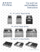
Product Specifications

WARNING: To reduce the risk of tipping the
appliance by abnormal usage or improper
door loading, the appliance must be secured
by properly installing the anti-tip device
packed with the appliance. To check the
installation remove the right top burner grates
and pan and verify that the anti-tip device is
engaged in the backguard slot.
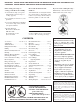
FIVESTAR
INSTALLATION INSTRUCTIONS
Please read these instructions
before attempting to install this
range
Unpacking
Check the range carton for visible
damage. If there is damage or even
creases in the carton contact the
carrier, request an inspection, and file
the appropriate freight claim. Do not
refuse shipment. Responsibility for
shipping damage is with the carrier
and the dealer or end user. Cut the
shipping straps then carefully lift the
carton up from the range. This will
help eliminate possible damage to the
backguard that is packed in the top of
the range carton.
Remove, unwrap, and temporarily lay
aside any parts that are not attached
to the range. Make sure no parts are
left in the carton for accidental
disposal. Carefully inspect the range
for damage.
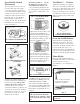
The standard top (not sealed) burners
are held in place with a screw to
protect them while in transit. These
shipping screws are to be removed to
give proper top burner operation and
allow easy removal.
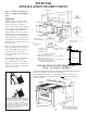
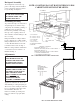
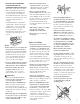
INSTALLATION OF ANTI-TIP BRACKET
ON 24”, 30” AND 36” MODELS
1) PLACE RANGE IN PROPER LOCATION WITH BACK OF RANGE AGAINST REAR WALL.
2) ADJUST LEG LEVELERS TO MATCH COUNTER HEIGHT.
3) REMOVE RANGE AND INSTALL ANTI-TIP BRACKET TO WALL, SEE NOTE, FIG. 2.
4) REINSTALL RANGE. ANTI-TIP BRACKET FLANGE MUST
ENTER SLOT IN BACK TO
PREVENT TIPPING.
3
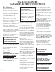
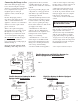
40” MINIMUM
6”
MINIMUM
13”
MAXIMUM
WIDTH OF
RANGE
18” MINIMUM
110V ELECTRICAL
CONNECTION AREA
SURFACE
MOUNT
CABINET CUT-OUT
24” RANGE = 24 3/16” 48” RANGE = 48 3/16”
30” RANGE = 30 3/16” 60” RANGE = 60 3/16”
36” RANGE = 36 3/16”
REAR WALL CLEARANCE
BACKGUARD HEIGHT (A): 11”
REAR WALL SPACING (B) ABOVE COOKING SURFACE: 0”
BACKGUARD HEIGHT (A): 4”
REAR WALL SPACING (B) ABOVE COOKING SURFACE:
1” ON SEALED BURNER MODELS
0” ON STANDARD BURNER MODELS
240V DUAL FUEL
MODELS ONLY
ANTI-TIP
BRACKET
NOTE:
ADD TO VERTICAL DIMENSION
DISTANCE BETWEEN CABINET
BOTTOM & FLOOR SURFACE
C SLOT IN
BACK
FIG. 2
BOTTOM OF
SIDE PANEL
FLOOR
UP
DOWN
3 1/2”
28 7/8”
EXHAUST
VENTILATION
*NOTE:
FOR HARD PIPING
SEE PAGE 5.
FLUSH
MOUNT
36”
2”
1 1/2”
2
6”
5”
5”
1”
34”
24”
5”
2”
*SEE NOTE
FIG. 1
WALL
C
LEARANCES
A
B
0” Clearance
0” Clearance
B
A