OPERATING INSTRUCTIONS MANUAL (Please retain for future reference) For FVO-400TR INDIRECT FIRED HEATER TRAILER CERTIFIED FOR USE IN CANADA AND U.S.A. As per CSA B140.8 Portable Oil Fired Heaters / CSA B140.0 2003 Oil Burning Equipment UL733 Oil Fired Air Heaters Construction Heaters Unattended Type. FLAGRO INDUSTRIES LIMITED ST.
GENERAL HAZARD WARNING: FAILURE TO COMPLY WITH THE PRECAUTIONS AND INSTRUCTIONS PROVIDED WITH THIS HEATER, CAN RESULT IN DEATH, SERIOUS BODILY INJURY AND PROPERTY LOSS OR DAMAGE FROM HAZARDS OF FIRE, EXPLOSION, BURN, ASPHYXIATION, CARBON MONOXIDE POISONING, AND/OR ELECTRICAL SHOCK. ONLY PERSONS WHO CAN UNDERSTAND AND FOLLOW INSTRUCTIONS SHOULD USE OR SERVICE THIS HEATER. THE IF YOU NEED ASSISTANCE OR HEATER INFORMATION SUCH AS AN INSTRUCTIONS MANUAL, LABELS, ETC. CONTACT THE MANUFACTURER.
TABLE OF CONTENTS Trailer Check List…………………………………………………… 4 Towing Instructions…………………………………………………. 5 FVO-400TR Set-up Procedure………………………………………6 Set-up Procedure (High Altitude)…………………………………...7/8 Nozzle Placement……………………………………………………. 9 Specifications……..………………………………………………….. 10 Trailer Preparation…………………………………………………. 11/12 Heater Start up……………………………………………………… 13 Troubleshooting……………………………………………………..
TRAILER CHECK LIST PLEASE PERFORM THE FOLLOWING STEPS TO YOUR FVO-400TR HEATER TRAILER TO ENSURE PROPER OPERATION. • Visually inspect outside & inside of trailer to ensure all instructions and decals are in place and legible. • Inspect the tires to ensure road worthy and have proper inflation. • Inspect hitch assembly and safety tow chains. • Inspect jack assembly to make sure it operates properly. • Make sure all trailer cabinet doors are closed before attempting to relocate trailer.
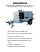
TOWING INSTRUCTIONS Before towing the FVO-400TR, please make sure you go over the following steps to ensure your trailer is road ready. 6 5 7 1 4 2 3 1. Hitch is securely attached to towing vehicle. 2. Safety chains are securely attached to towing vehicle. 3. Front jack is completely retracted. 4. Check all tires ensure they have adequate air pressure. 5. Make sure all ducting is removed from heaters and stored. 6. All doors are closed and secure. 7. Taillights are connected and operating.
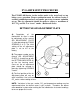
FVO-400TR SETUP PROCEDURE The FVOHC-400 heater in the trailer needs to be tested and set up before every operation. Proper combustion must be achieved using a certified combustion analyzer and smoke gun tester to ensure optimum set up. The air adjustment should be made to achieve a maximum of 10% CO2 and No. 1 or “trace” smoke.
SETUP PROCEDURE (HIGH ALTITUDE) When the FVO-400TR is required to operate over 2000 feet above sea level there will be necessary adjustments needed to burn efficiently with thinner air. Please review the following chart as a starting point; please note that a combustion analyzer & smoke gun will be required to achieve optimum set up. ACTUAL FIRING RATE +/- 5% 2.11 GPH NOZZLE SIZE PUMP PRESSURE TURBULATOR SETTING AIR DAMPER SETTING ALTITUDE RANGE 1.75 X 60W 145 PSI 2.5 3.1 2.41 GPH 2.61 GPH 2.
INSERTION / REMOVAL OF DRAWER ASSEMBLY A) To remove drawer assembly, loosen SCREW (3), then unplug CONTROL BOX (1) by carefully pulling it back and then up. B) Remove the AIR TUBE COVER PLATE (5) by loosening the two retaining SCREWS (4). C) Loosen SCREW (2), and then slide the complete drawer assembly out of the combustion head as shown. D) To insert drawer assembly, reverse the procedure in items A to C above, and then attach fuel line to the pump.
NOZZLE PLACEMENT A) Remove the NOZZLE ADAPTER (2) from the DRAWER ASSEMBLY by loosening the SCREW (1). B) Insert the proper NOZZLE into the NOZZLE ADAPTER and tighten securely (Do not over tighten). C) Replace adapter, with nozzle installed, into drawer assembly and secure with screw (1).
SPECIFICATIONS Model …………………………… FVO-400TR Input ……………………………... 390,000 BTU Engine …………………………… Yanmar Liquid Cooled Diesel Electric start/ glow plugs Battery charging alternator Heavy duty Radiator & Air Cleaner Remote Oil Drain Generator………………………… 6 kw @ 1800 rpm (10.7 HP) Single phase-120V Instrument panel including Hour Meter Fuel …………………………….... No.1, No. 2, Diesel Fuel Pressure ………………..........170 psi @ 0-2000 ft Nozzle …………………………… 2.00 x 60W (Delavan) @ 0-2000 ft Fuel Tank ………………………..
TRAILER PREPARATION FOR START-UP PLEASE REVIEW TRAILER CHECKLIST, FVO-400TR SETUP & GENERATOR MANUAL BEFOR PROCEEDING OPEN & SECURE REAR GENERATOR ACCESS DOOR OPEN OUTLET DOOR & ATTACH DUCTING TO HEATERS
OPEN HEATER START UP DOOR INSPECT FUEL GAUGE FOR SUFFICIENT LEVEL OF FUEL
MAKE SURE BATTERY LOCK OUT IS TURNED OFF, AND TURN KEY ON CONTROL PANEL TO START
HEATER START UP INSTRUCTIONS: 1. Be sure the “switch” is in the “OFF” position. 2. Start generator, verify heater inlet and outlet door are in the open position. 3. Move switch to “MANUAL” position for manual control. 4. Move switch to “THERMOSTAT” position for thermostatic control. OR Please Note: 1. If using Thermostat on unit, unit must be started in Thermostat position.
IF HEATER FAILS TO START: 1. Press manual reset button at rear of burner. (Red button) 2. Check fuel level gauge for sufficient amount of fuel. 3. Make sure there are no air blocks in fuel lines or filter. Bleed lines if required. 4. Ensure power supply plug is connected properly. 5. Check for dirty fuel filter or blocked fuel supply line. 6. Check burner nozzle assembly. 7. Make sure the burner control box does not need to be reset.
MAINTENANCE: 1. Every construction heater should be inspected before each use, and at least annually by a qualified service person. Incorrect maintenance my result in improper operation of the heater and serious injury could occur. 2. The hose assemblies shall be visually inspected prior to each use of the heater. If it is evident there is excessive abrasion or wear, or the hose is cut, it must be replaced prior to the heater being put into operation.
TEMPERATURE FEELER GAUGE ADJUSTMENT (ATTACHED TO FAN SWITCH) The temperature feeler gauge is required to be always touching the heater exchanger. The temperature feeler gauge controls the air flow over the fan switch, which eliminates any unnecessary fan cycling. The temperature feeler gauge can be adjusted for different outside temperatures, by rotating the location of the temperature feeler gauge holes. This will provide maximum performance of the unit in different applications.
BURNER WIRING DIAGRAM ELECTRICAL CONNECTIONS It is advisable to leave the control box off the sub-base while completing the electrical connections to the burner.
ELECTRODE SETTING OIL LINE CONNECTIONS Note: Pump pressure must be set at time of burner start-up. A pressure gauge is attached to the PRESSURE PORT (8) for pressure readings. Two PIPE CONNECTORS (5) are supplied with the burner for connection to either a single or a two-pipe system. Also supplied are two ADAPTORS (3), two female 1/4” NPT, to adapt oil lines to burner pipe connectors. All pump port threads are British Parallel Thread design.