OPERATING INSTRUCTIONS MANUAL (Please retain for future reference) For FVN/P-200 INDIRECT FIRED SPACE HEATERS CERTIFIED FOR USE IN CANADA AND U.S.A. As per Standard ANSI Z83.7/CSA 2.14 2000 Gas Fired Construction Heaters / Unattended Type. FLAGRO INDUSTRIES LIMITED ST.
Version 2009-1 GENERAL HAZARD WARNING: FAILURE TO COMPLY WITH THE PRECAUTIONS AND INSTRUCTIONS PROVIDED WITH THIS HEATER, CAN RESULT IN DEATH, SERIOUS BODILY INJURY AND PROPERTY LOSS OR DAMAGE FROM HAZARDS OF FIRE, EXPLOSION, BURN, ASPHYXIATION, CARBON MONOXIDE POISONING, AND/OR ELECTRICAL SHOCK. ONLY PERSONS WHO CAN UNDERSTAND AND FOLLOW THE INSTRUCTIONS SHOULD USE OR SERVICE THIS HEATER. IF YOU NEED ASSISTANCE OR HEATER INFORMATION SUCH AS AN INSTRUCTIONS MANUAL, LABELS, ETC. CONTACT THE MANUFACTURER.
This heater is designed and approved for use as a construction heater under Standard ANSI Z83.7/ CGA 2.14. 2000. We cannot anticipate every use which may be made of our heaters. CHECK WITH YOU LOCAL FIRE SAFETY AUTHORITY IF YOU HAVE QUESTIONS ABOUT APPLICATIONS. Other standards govern the use of fuel gases and heat producing products in specific applications. Your local authority can advise you about these. SPECIFICATIONS Model …………………………………………………….….
INSTALLATION: The installation of this heater for use with natural gas shall conform with local codes or, in the absence of codes, with the National Fuel Gas Code ANSI Z223.1/NFPA 54 and the Natural Gas and Propane Installation Code, CSA B149.1-00. This heater must be installed by a qualified gas technician, following local codes published by the authority having jurisdiction.
PRESSURES: MAXIMUM INLET PRESSURES: LP: NG: 13.0 IN. WC. 10.0 IN. WC. MINIMUM INLET PRESSURES: LP: NG: 8.0 IN. WC. 7.0 IN. WC. This heater must be supplied by pressures indicated on the approval label. Over pressure may cause controls to fail. DO NOT supply this unit with more than ½ psig (14.0 in. W.C.) Note: A second stage regulator must be installed if the supply pressure exceeds ½ psig. FUEL: This heater will operate on propane OR natural gas – NOT BOTH.
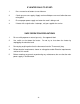
FV SERIES CONSTRUCTION HEATER – VENTING REQUIREMENTS 1. VERTICAL FLUE TERMINATIONS B A VERTICAL FLUE RUN D HORIZONTAL FLUE RUN - RISE RATIO 1:10 FLUE OUTLET OF HEATER 2. HORIZONTAL FLUE TERMINATIONS B C FLUE OUTLET OF HEATER EXTERIOR WALL A - VENT TERMINATION MUST BE A MINIMUM OF 2FT HIGHER THAN ANY POINT WITHIN 10FT. B - MAXIMUM HORIZONTAL RUN IS 30FT.
CLEARANCE TO COMBUSTIBLES: Model FVN/P-200 TOP FRONT SIDES REAR FLUE PIPE 3 ft 10 ft 1 ft 2 ft 3 ft MAINTENANCE: 1. Every construction heater should be inspected before each use, and at least annually by a qualified service person. Incorrect maintenance my result in improper operation of the heater and serious injury could occur. 2. The hose assemblies shall be visually inspected prior to each use of the heater.
START UP INSTRUCTIONS: 1. Be sure the switch is in the “OFF” position. 2. Ensure electrical cord is grounded and heater is on a level surface. 3. Plug in supply cord to 115v, 15amp outlet. 4. Make sure Smart Indicator Light is green, if not green, please refer to the “Power Supply Indicator Label” before proceeding with start up. 5. Move switch to “MANUAL” position for manual control. 6. Move switch to “THERMOSTAT” position for thermostatic control. Please Note: 1.
IF HEATER FAILS TO START: 1. Press manual reset button at rear of burner. 2. Check gas pressure supply. Supply and manifold pressure must follow those on rating plate. 3. Ensure proper power supply and extension cord is being used. 4. If heater fails to ignite after 3 attempts, call your supplier for service. SAFE OPERATION PRECAUTIONS: 1. For use with propane or natural gas only. See approval label. 2. Use switch to shut down the heater. unplugging the electrical cord. 3.
COMBUSTION AIR ADJUSTMENTS: NOTE: Proper combustion air adjustment must be achieved using a certified combustion analyzer to ensure complete combustion. The air adjustment should be made to achieve 10% CO2 on natural gas and 12% CO2 on propane. SETTING THE AIR ADJUSTMENT PLATE A) Regulation of the combustion air flow is made by adjustment of the manual AIR ADJUSTMENT PLATE (1) after loosening the FIXING SCREWS (2 and 3).
TEMPERATURE FEELER GAUGE ADJUSTMENT (ATTACHED TO FAN SWITCH) The temperature feeler gauge is required to be always touching the heater exchanger. The temperature feeler gauge controls the air flow over the fan switch, which eliminates any unnecessary fan cycling. The temperature feeler gauge can be adjusted for different outside temperatures, by rotating the location of the temperature feeler gauge holes. This will provide maximum performance of the unit in different applications.
Model 200 A B C F G *G1 H Inches 9 3/16 10 11/16 6 11/16 11 5/8 3 15/16 10 3 9/16 mm 233 272 35 295 85 255 91 *G1 is for LBT version Gasket thickness is 4 millimeters - 12 -
ELECTRODE AND FLAME PROBE ADJUSTMENTS IMPORTANT: Do not turn the ignition electrode. Leave it as shown in the drawing. If the ignition electrode is put near the ionization probe, the amplifier of the control box may be damaged.
- 14 -
- 15 -
FV-200 SERIES - WIRING SCHEMATIC L1 POWER INDICATOR FAN SWITCH T1 115 VAC T3 N T4 FAN MOTOR G G SWITCH REMOTE THERMOSTAT REAR HIGH LIMIT SWITCH FRONT HIGH LIMIT SWITCH BURNER X G - 16 - RED LIGHT
PARTS LIST FVN-200 & FVP-200 INDIRECT FIRED HEATERS PART NUMBER DESCRIPTION FV-201 1/2 HP Fan Motor FV-202 15” Fan Blade FV-203 12” Wheel FV-204 12” Power Cord c/w Plug End FV-205 SS Heat Exchanger FV-206 High Limit Switch (Outlet) 250F FV-407A Fan Limit Switch (Adjustable) FV-407G Fan Limit Silicone Gasket FV-207 Lockable Caster Wheel FV-208 Fan Motor Canopy FV-409 Toggle Switch (on control box) FV-411 Red Light (on control box) FV-214 Thermostat Plug (on control box) FV-215 F
ACCESSORIES FV-D12 12” X 12ft Canvas Ducting FV-THA Thermostat c/w 25FT Cord FVN-227 LP to NG Conversion Kit FVP-228 NG to LP Conversion Kit FV-VK 6” x 3FT C-Vent c/w Rain Cap Version 2009-1 - 18 -