
User's Manual


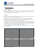
Table Of Contents
- 1. Introduction
- 2. General Specification
- 3. Pin Definition
- 4. Physical Interfaces
- 5. Electrical Characteristic
- 6. Reference Design
- 7. Mechanical Characteristic
- 8. Recommended PCB Layout and Mounting Pattern
- 9. Recommended Reflow Profile
- 10. Ordering Information

FLC-BTM403 Series User Manual
Flaircomm Technologies Confidential
-10-
4. Physical Interfaces
4.1 Power Supply
The transient response of the regulator is important. If the power rails of the module are supplied
from an external voltage source, the transient response of any regulator used should be 20μs or less.
It is essential that the power rail recovers quickly.
4.2 Reset
The module may be reset from several sources: RESET pin, power-on reset, a UART break
character or via a software configured watchdog timer.
The RESET pin is an active high reset and is internally filtered using the internal low frequency
clock oscillator. A reset will be performed between 1.5 and 4.0ms following RESET being active. It
is recommended that RESET be applied for a period greater than 5ms.
The module has an internal reset circuitry, which keeps reset pin active until supply voltage has
reached stability in the start up. This ensures that supply for the flash memory inside the module will
reach stability before BC4 chip fetches instructions from it. Pull-up or pull-down
r
e
s
i
s
to
r
should
not be connected to the reset pin to ensure proper star up of
module
.
At reset the digital I/O pins are set to inputs for bi-directional pins and outputs are tri-state. The PIOs
have weak pull-downs.
Pin Name / Group Pin Status on Reset
USB_DP Input with PD
USB_DN Input with PD
UART_RX Input with PD
UART_CTS Input with PD
UART_TX Tri-state output with PU
UART_RTS Tri-state output with PU
SPI_MOSI Input with PD
SPI_CLK Input with PD
SPI_CSB Input with PU
SPI_MISO Tri-state output with PD
PCM_CLK Input with PD
PCM_SYNC Input with PD
PCM_IN Input with PD
PCM_OUT Tri-state with PD
RESETB Input with PU
PIOs Input with weak PD
AIOs Output, driving low