70-81 Camaro Rack & Pinion Cradle System Index For safety disconnect battery cables and ensure that vehicle is properly supported by jack stands. NOTE: Hoses (FR1610) Pump Mounting Brackets (FR1611) is sold separately and is not included in this kit. Factory inner and outer tie rod ends must be used with this rack and pinion kit. Before paint or powder coating of the rack and pinion cradle system we recommend that you pre-fit the system to ensure proper fit.
70-81 Camaro Rack & Pinion Cradle System P/N 100202 100205 100207 FR1614 FR1717DD FR1789P-2 FR1850-22 FR20114-K FR20118 FR2644 FR30001 FRDMDCL FRPMPSB-V DESCRIPTION QTY KIT, HDW CRADLE CAMARO 70-81 ASM, JOINT HEIM Ø.
70-81 Camaro Rack & Pinion Cradle System If using a Flaming River Steering Column it is recommended that before any disassembly you should first verify the wiring for your turn signals and ignition switch to ensue proper operation. Color Verification to be completed before disassembly Before disconnecting the turn signal and the ignition connectors verify the wiring color to ensure proper operation. The colors listed with the ignition switch diagram below are from a stock wiring system.
70-81 Camaro Rack & Pinion Cradle System Original Column Removal Only perform these steps if using a new Flaming River Steering Column 1) 2) 3) 4) Disconnect the column wiring connectors. Remove the bolts that hold the column floor mount to the firewall. Support the column and remove the bolts that retain the under dash mounting clamp. Remove the factory steering column from the vehicle.
70-81 Camaro Rack & Pinion Cradle System 3) Remove the cotter pins and castle nuts and separate the outer tie rod ends from the spindles. 4) Next remove the steering linkage from the car. 5) If you have power steering remove the lines from your power box, pump and pump brackets.
0-81 Camaro Rack & Pinion Cradle System Installation of Flaming River Column Note: The factory OEM floor mount is fixed to the steering column. Modification to the factory floor mount is required to hold the new steering column in place. (See example below) 1) Remove the two screws that hold the dash mount together and separate. 2) Take the upper portion of the mount and place it in the stock mounting location, next using the factory mounting hardware snug the mount in place.
70-81 Camaro Rack & Pinion Cradle System Electrical System Notes Caution: Before disconnecting your original steering column wiring harness please verify each wire color and function on the worksheet below. Some wire colors may vary from year to year.
70-81 Camaro Rack & Pinion Cradle System 3) To install the wheel adapter run the horn contact wire through the hole for the canceling cam and place the adapter on to the splined column shaft. 4) Tighten the adapter-retaining nut until the adapter is approximately 1/16” away from the column shroud.
70-81 Camaro Rack & Pinion Cradle System 2) To install the Flaming River rack and travel bar system rotate the travel bar over the lip of the cross member, next position the rack into place and install the rack to the cradle using the mounting brackets provided. Once you have adjusted the pinion angle tighten the 4 mounting bracket bolts and the 2 ¼-20 set screws to lock the rack in place.
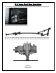
70-81 Camaro Rack & Pinion Cradle System 4) To install the outer tie rod ends into the spindles you must load the front suspension. (Securely placing jack stands under the lower control arms and lowering the car onto the jack stands accomplishes this.) Install the outer tie rod ends into the spindle and tighten the castle nuts to 30-40 ft lbs. Make sure to install cotter pins into the castle nut and tie rod end and bend the tabs over for security. Universal Joint System.
70-81 Camaro Rack & Pinion Cradle System 2) We recommend the use of ¾” wood dowel rod to mock up the steering shaft to obtain the correct length of the shafts. 3) Install your shaft kit and snug each set screw so that it will leave a mark in the shafts. 4) Remove shaft and dimple each setscrew mark using a ¼” drill bit. (As shown below.) 5) Re-install the shafts using red loc-tite thread locker on the set screw threads. Tighten each setscrew to 25 ft. lbs. Tighten all lock nuts securely.