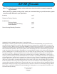
63-82 Corvette Note: For safety disconnect battery cables and ensure that the vehicle is properly supported by jack stands. Before painting or powder coating of the cradle, we recommend that you pre-fit the entire system to ensure proper fitment for your application.
Qty Part Number Description 100776 Power Rack and Cradle Assembly 1 100780 Fitting 5/8-16 x 6AN 1 100781 Hardware Mounting Kit 1 FR1796 3/4”DD x 1”-48 Double U-Joint 1 FR1810KA Angled Bracket with Bearing 1 FR1851-10 3/4”DD 10” Long Steel Shaft 1 FR1969 FR Power x 3/4”DD Chrome Moly 1 U-Joint 2 Flaming River Industries 1-800-648-8022 FRxxxx Rev.
2 4 3 5 6 1 ITEM NO. QTY. PART NO. 1 1 100781 2 1 100890 3 1 FR1796 4 1 FR1810KA 5 1 FR1851-10SS 6 1 FR1969 DESCRIPTION KIT, HDW MTG CRADLE VETTE PWR ASM, CRADLE/RACK CORVETTE 1963-82 RHD ASM, U-JOINT DBL 3/4DD X 1-48 ASM, BRKT MTG/BEARING SUPT SHAFT, CUT SS 3/4DD X 10.00 ASM, U-JOINT 3/4DD X FRPOWER CHROMOLY 1963 - 1982 Corvette Cradle and Shaft Assembly 3 Flaming River Industries 1-800-648-8022 FRxxxx Rev.
Original System Removal 1) 2) For safety, disconnect your battery. Before disassembly measure from zirc to zirc on the outer tie rod ends. Write this dimension down for future reference. Before disassembly measure from zirc to zirc on the outer tie rod ends 3) Remove the bolt that retains the coupler to the factory steering column shaft. Spread the flange and then remove the rag joint from the car. 4) 4 Flaming River Industries 1-800-648-8022 FRxxxx Rev.
5) Remove the bolts that hold the steering box to the frame, and then remove the box from the car. Next remove the bolts that hold the idler arm bracket to the frame, the outer tie rod ends from the spindle arms, then remove the steering linkage from the car. 6) If your vehicle has power steering... Remove the power steering lines from the pump to the power steering control valve and drain your system.
Flaming River Rack and Pinion Installation 1) Install the rack and pinion cradle by sliding it into place between the frame rails. Using the new hardware, install the three (4) 3/8” bolts on the drivers side using the original holes from the steering gear box and the additional hole that is located under the factory motor mount. On the passenger side use idler arm bolts and the additional hole that is located under the factory motor mount (3) 3/8” bolts and tighten all the bolts and nuts to 40-45 ft. lbs..
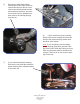
Flaming River Rack and Pinion Installation 3) Install the OEM inner tie rod end into the Flaming River inner tie rod end on the new power rack. Note: If using the original parts some adjustment of the tie rod assembly may be required when connecting the to the spindle arm and the travel bar. Outer Tie Rod End 4) Inner Tie Rod End To install the outer tie rod end into the spindles you must load the front sus- pension.
Universal Joint Installation Note: Depending on u-joint alignment, It may be neccessary to shorten the factory steering column by either trimming the the steering column shaft (63-66) or collapsing the column shaft (67-82) until the splines meet teh end of the column tube. (example shown in picture to left). 1) Install the support bearing bracket onto the rear cradle mounting bolt. 2) Using a 3/4” wooden dowel rod, mock up the steering shaft to obtain the correct shaft lengths and u-joint angle.
Power Steering Bleeding Procedure 1) Raise the front wheels off the ground and support the vehicle on jack stands. 2) Turn the steering wheel to the left lock and fill the reservoir and let the vehicle sit for 2 minutes. 3) WITH THE ENGINE OFF - Rotate the steering wheel lock to lock 20-25 times, while rotating the wheel have someone monitor the fluid level and fill as necessary.