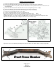
INDEX NOTE: Before beginning you must first measure the width of your front end from LEFT outer tie rod end zirc to the RIGHT outer tie rod end zirc to determine the overall width of your front end. Write dimension here for further reference NOTE: Part number ES381RL 68-69 Camaro Outer Tie Rod Ends must be used with this rack and pinion kit.
Power Kit Page 2 of 11 012710 JJ/RD/RP/BC
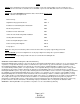
Parts Inventory Qty Part No.
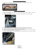
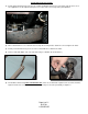
Original Steering System Removal 1) Remove the pitman nut and remove the pitman arm from the steering box. 2) Remove the nuts that retain the outer tie rod ends and remove the tie rods from the spindle arm. 3) If you have the power assist system you must also disconnect the slave cylinder from the chassis and remove the mounting bracket. 4) Remove the bolts that retain the idler arm and remove the steering linkage from the car.
Original Steering System Removal Con’t 14) Remove the two bolts that retain the factory front spindle arms to the spindle and remove the arms. Installation of Flaming River Column 1) Slide the floor mount that is included in the kit over the column tube and then slide the original floor seal and floor plate over the column tube. 2) Slide the column through the firewall so that the end of the column tube is about a ¼” past the firewall.
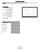
Connecting Electrical System Caution: Before disconnecting your original steering column wiring harness please verify each wire color and function on the worksheet below. Some wire colors may vary from year to year.
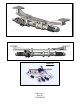
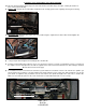
Installation of the Flaming River Power Rack and Cradle 1) Center the rack by turning it all the way to the left. Next turn the rack all the way to the right, counting the number of turns. Then go back half way. 2) Driver’s side: Hold up the rack mounting cradle where the steering gear box was originally and snug the mounting hardware. 3) Passenger side: Mount the passenger side of the cradle using the original holes from the idler arm and tighten the four 5/16” mounting bolts.
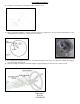
Header Universal Joint System. 1) Install support-bearing mount onto the rear cradle bolt. (Diagram below). Note: The angle of this mount is set for most applications. Some adjustment may be necessary for the correct angle and u-joint alignment. Support Bearing Bracket 2) We recommend the use of ¾” dowel rod to mock up the steering shaft to obtain the correct length of the shafts. 3) Install your shaft kit and snug each set screw so that it will leave a mark in the shafts.
Steering Wheel Installation 1) Install horn contact kit into canceling cam tube and turn to lock. 2) Align steering wheel adapter so that the canceling cam hole is at approx the 11 O’clock position and that one of the steering wheel mounting holes is at the 12 O’clock position. 3) To install the wheel adapter run the horn contact wire through the hole for the canceling cam and place the adapter on to the splined column shaft.
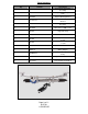
Bleeding the System 1) Raise the front wheels off the ground and support vehicle on jack stands. 2) Turn the wheel to the left lock and fill the reservoir with high-quality power steering fluid and allow vehicle to sit for 2 minutes. 3) With the engine off and someone checking the fluid level rotate the steering wheel lock to lock 20 times filling with fluid as necessary. 4) With the engine running, rotate the steering wheel back and forth from lock-to-lock. Repeat several times.
Page 11 of 11 012710 JJ/RD/RP/BC