www.ff3dp.com ZHEJIANG FLASHFORGE 3D TECHNOLOGY CO., LTD.
www.ff3dp.com Contents 1 What's Included in the Box? 2 2 Un-boxing 2 3 Initial Hardware Installation 6 4 Software Installation 8 5 USB Connection & Temperature Setting 13 6 Filament 16 6.1 Install Filament 16 6.2 Feeding the Filament Using the LCD Screen 17 6.3 Withdrawing the Filament Using LCD Screen 18 6.4 Feeding the Filament Using Replicator G Control Panel 18 6.
www.ff3dp.com WARNING Flashforge sets the power supply to default 230v before leaving factory. If voltage in your location is between 90v to 132v, please switch the power setting from 230v to 115v before you plug in the power. Failure to do so will damage the motherboard. You can find the power source at the bottom of Creator Pro. The red box is where the power setting is located: PRECAUTIONS: Please make sure to read this page carefully prior to setting up and operating the Creator Pro.
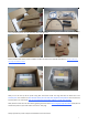
1 What's Included in the Box? Along with your Creator Pro 3D printer, the box also contains the following: In the two long boxes on the top of the package, you’ll find: Power cord x 1pc, USB A to B cable x 1pc, Sensor Line x 1pc, Filament guide tube x 2 pcs. Filament spool holder x 2 pcs.
You will find another box within the relevant assembly tools under the two long boxes. You should assemble the Acrylic cover yourself and please check the assembly video in the SD card. Please hold both sides of the printer and take it out after you take out the side EPE of Creator Pro. Please make sure you only can hold the frame. Now you can see the top of the printer along with more boxes inside. The large box with the black wire is the accessory box.
Now, open the accessory box and remove the accessory sleeve. You will find the dual extruder heads in the protective packaging along with the black cable, carefully remove it and place it on your work surface. Remove the cardboard packing material and take the accessory box from the printer, set it aside for later. The build platform should now be visible. It is an aluminum plate covered in a thin polyamide film. This is the surface that your objects will be printed on. Note: Remember not remove the film.
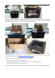
3 Initial Hardware Installation WARNING Flashforge sets the power supply to default 230v before leaving factory. If voltage in your location is between 90v to 132v, please switch the power setting from 230v to 115v before you plug in the power. Failure to do so will damage the motherboard. You can find the power source at the bottom of Creator Pro. The red box is where the power setting is located: To do this, begin by carefully placing the Creator Pro on one of its sides so that the bottom is exposed.
Next is the installation of the spool holder. Install one on each side. The installation of the spool holder is very simple – just insert it into the circular opening and tighten the nut behind. Then install the filament guide tube to the empty spot on the extruder. Place one end of the guide tube into the hole. The hardware installation is almost complete. Next, with the power switch in the OFF position, confirm that the power cord is plugged into the power outlet next to the power switch.
Congratulations! You have completed the initial hardware installation! If you're ready to start printing, proceed to the next step: Software Installation. 4 Software Installation SPECIAL NOTES TO WIN 8 USERS BEFORE SOFTWARE INSTALLATION Win 8 users please make sure that you have disabled the Driver Signature Enforcement setting before installing the ReplicatorG software. Below is a video link showing you how to accomplish this: http://www.youtube.
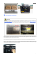
After opening ReplicatorG software, click on Machine to select your Machine Type. Choose The Replicator Dual for Creator Pro dual extruder machine. After selecting the appropriate machine type, click on GCode on the top navigation bar, and under GCode Generator, select Skeinforge(50). The following gives an introduction on how to import files (.STL) into the Replicator G software and then generate Gcode to print your creation. Click File > Open, then browse and select the file (.
When the object is imported you may find that it is not on the virtual build platform or even on the screen, using the function keys indicated by the blue boxes in the illustration above, you can change the camera angle and reposition the object onto the center of the build platform. Once you've done this, the next step is to generate the Gcode. This is achieved by clicking on the button (Generate GCode) at the bottom of the panel.
A. Slicing Profile: select Replicator slicing defaults for ABS printing, then select Replicator 2 slicing defaults for PLA printing. B. This tells the printer which extruder to use for a dual-extruder head printer, either the left or right head can be selected. C. If your sample will have any hanging surfaces, it is recommended to have support. Select None indicates that there is no support. Exterior means surface support. Full support means all support. D.
Click File > Preferences, then click Select Python interpreter under the Advanced tab. A window will pop up. Navigate to the Python installation directory, and select python.exe and click Open.
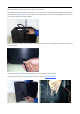
The machine will now work as normal when generating Gcode, and the Python error message will not pop up again.In the next section, we will start a preliminary test on the machine’s connections, and heat the platform and extruder so that the extruder is ready for its first print. 5 USB Connection & Temperature Setting First, connect the machine and computer with the provided USB A to B cable. The USB port on the machine is bound by the box in the below image.
Locate the software driver shown in the blue box above. Right click and select Update Driver Software. Click Browse my computer for driver software to find the location of ReplicatorG0040 on your system.
Click FTDI USB Drivers in the driver folder before confirmation and click OK. The drivers will then be installed. The next step is to link the printer. Rescan the serial ports and select the one that appears on your machine (on our test machine the port was COM10, but different computers vary). Now we can link the machine to the computer.
Input the following target values: 220°C for the extruder and 115°C for the heating platform. After entering the values, the platform will start to warm up. When the extruder temperature reaches 50°C, the cooling fan will be activated and the current temperature value will display to the right as shown below.
When you have removed the guide tube you can remove the filament that is inside the guide tube. To avoid any blockages during printing, please ensure that the two threads are loaded from the middle. There are two wire trays, one runs clockwise and the other one runs counter - clockwise, as shown below: There are two ways of feeding the filament into the extruder head, one is using the LCD screen on the printer itself and the other is by using the control panel on the Replicator G software. 6.
Feed operation with LCD screen 4. Select Filament loading; press the OK key of the keypad. The display will show: ▶ Load Right Unload Right Load Left Unload Left 5. Select the appropriate side of the extruder you wish to load(Left or Right for models with dual extruders). Press the OK key again on the keypad. The display will indicate: I'm heating up my extruder!” At this time, the temperature of the right nozzle is being heated up.
To heat the right extruder and feed material, click the right extruder on the upper right corner of the control panel and manually modify the temperature in the “Right Target” setting for the extruder temperature control changing the temperature to 220°C. A red line will be plotted in the temperature map. When the actual (Current) temperature reaches 220°C you can pull the filament out. 6.
need to click OK, the extruder will move to next point. Attention please: when the 2 knobs level finished, you only need to click Print Another Copy, then the extruder will continue to the third point, four points can be level finished Now, let’s start the initial print. Click File > Examples and then select the 20mm_Calibration_Box.stl. The preview interface will then appear along with a virtual impression of the 20mm cube on the virtual printer bed.
Next click Generate GCode, a dialogue box will pop up, after inputting your chosen parameters the Gcode will be generated. Please refer to EXPLANATION OF GCODE SETTINGS. A loading bar will then appear showing the progress of the Gcode generation.
After the Gcode is generated, the temperature of the bottom plate needs to be changed if you print PLA filament. See below for the required modification. First, select Gcode as shown highlighted in the illustration below and change M109 S110 to M109 S50 to set the HBP temperature at 50°C. Then click File > Save to save this modification. If you print ABS filament, then no HBP temperature modification is needed.
8 Dual Extruder Print Open ReplicatorG and select Gcode > Merge .stl for Dual Extrusion. You will see following: Click on the first Browse button to locate and select the file for left extruder; and then click on the second Browse button for right extruder. For example, you can find the examples folder in its installation path. Open the folder examples select Two_color_world_a.
If you want to print dual colors with ABS filament, select Replicator slicing defaults under the Slicing Profile column, and lower the Feedrate to 60 and Travel Feedrate to 80. Click the Generate Gcode option for both boxes. After the Gcode is generated, click on the gcode tab as highlighted below and change HBP temperature to 50 if you are printing with PLA and save this modification by going to File > Save. Click on the following button to export .x3g file for SD card print.