FlashForge Corporation User Guide FlashForge Creator Pro 3D Printer User Guide Creator Pro User Guide | www.FlashForge.
Contents Contents..........................................................................................................................2 Preface............................................................................................................................ 3 Introduction.................................................................................................................... 4 Notice....................................................................................................
Preface Note: Each device must be tested before leaving factory. If there are some residues in extruder or some tiny scratches on the build tape, it is normal and won’t affect the printing quality. On the completion of this User Guide, thanks all FlashForge engineers and the FlashForge 3D printer users for their unremitting efforts and sincere assistance. The FlashForge Creator Pro User Guide is designed for the Creator Pro users to start their printing journey with FlashForge Creator Pro.
Introduction Notes: ·Please read FlashForge Creator Pro 3D Printer User Guide carefully before use. ·The User Guide is written based on Windows 7 OS. ·The version of the FlashPrint is the latest. The FlashForge Creator Pro 3D Printer User Guide contains the information needed for you to set up and use this device. This User Guide includes the following parts: Preface, Introduction and Aftersale service.
Notice ! Notices: Read all the instructions in the manual and familiarize yourself with the FlashForge Creator Pro User Guide before setting-up and using. Failure to comply with the warning and instructions may result in individual injury, fire, equipment damage or property damage. PLEASE STRICTLY FOLLOW ALL THE SAFETY WARNINGS AND NOTICE BELOW ALL THE TIME. · Work Environment Safety ① Keep your work place tidy. ② Do not operate Creator Pro in the presence of flammable liquids, gases or dust.
and gloves away from moving parts. ④ Do not operate the device while you are tired or under the influence of drugs, alcohol or medication. ·Cautions ① Do not leave the device unattended for long. ② Do not make any modifications to the device. ③ To lower the build plate before loading/unloading filament. (The distance between the nozzle and build plate should be kept for at least 50mm) ④ Operate the device in a well-ventilated environment. ⑤ Never use the device for illegal activities.
filament from the brands accepted by FlashForge. · Filament Storage All polymers degrade with time. Do not unpack filament until necessary. Filament should be stored in clean and dry conditions. Legal Notice All the information in this document is subject to any amendment or change without the official authorization from FlashForge.
Chapter 1: 3D Printing Technology 3D printing refers to transforming three-dimensional models into physical objects that you can hold and touch. It is also called additive manufacturing because the 3D model is created by “adding” layers upon layers of material until the object is fully formed. Fused Filament Fabrication (FFF) is the most common method of 3D printing. It is also the method that the Creator Pro uses.
·From the Cloud The most popular way of obtaining a 3D model is to download it from websites that allow users to upload 3D models that they designed. E.g. www.thingiverse.com 1.1.2 Slice and Export the 3D Model Slice software is the software that prepares 3D models for printing and turns them into instructions for the 3D printers. FlashPrint is the slicing software used for the FlashForge Creator Pro. Using FlashPrint, you can prepare .stl files to be .x3g files for printing.
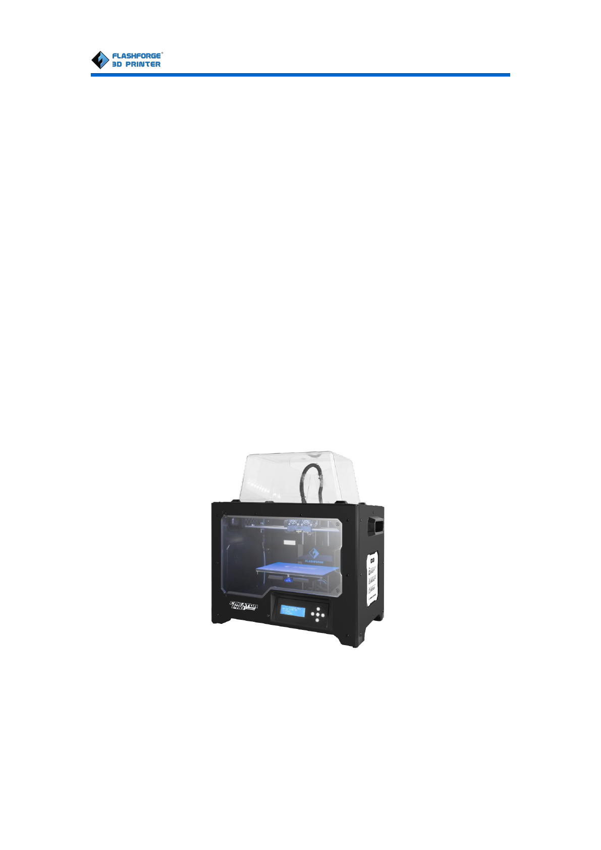
Chapter 2: About Creator Pro 2.1 About Your Creator Pro 2.1.1 Views 1.Z-axis guide rod 13.Turbofan 2.Extruder cable bunch 14.Turbofan baffle 3.Slot 15.Left nozzle 4.Y-axis guide rod 16.Right nozzle 5.Build plate 17.X-axis guide rod 6.Build platform 18.Filament guide 7.Leveling knob tube buckle 8.SD card slot 19.Spool holder 9.LCD panel 20.Power input 10.Buttons 21.Power switch 11.Cooling fan 22.Reset button 12.Spring presser 23.USB input 24.
2.1.
2.1.3 Terms Build Plate The surface on which the Creator Pro builds an object. Build Tape The blue tape that covers Creator Pro’s build plate so that the object can adhere to the build plate well. The three dimensional amount of space that an object Build Volume will use once it is completed. The largest build volume of Creator Pro is 227*148*150 Knobs under the build platform that are used for Leveling Knobs adjusting the distance between the nozzle and build plate.
2.1.4 Parameters Name Creator Pro Number of Extruder 2 Print Technology Fused Filament Fabrication(FFF) Screen LCD Panel Build Volume 227×148×150mm Layer Thickness 0.1 - 0.2mm Build Precision ±0.1-0.2mm Positioning Precision Z axis 0.0025mm; XY axis 0.011mm Filament Diameter 1.75mm(±0.07) Nozzle Diameter 0.
FlashForge Corporation Chapter 3: Unpacking (reference video:Creator Pro Unpacking) The Creator Pro was carefully packaged at FlashForge manufacturing facility. Please follow the unpacking steps laid out below. CAUTION Handle the package and its contents with extra care; do not use any unnecessary force. Do not remove the wrapping around the nozzle. It consists of a ceramic fiber fabric and heat resistant tape that helps to keep the nozzle at a constant temperature. 1.
3-2 3. (3-3)The FlashForge Creator Pro and its accessories will be displayed in front of you. Take the dual extruder out and place it onto a clean ground. Note: To avoiding scratching the dual extruder and affecting the printing precision, please do not put the nozzle onto the surface. 3-3 4. (3-4)Take the accessory foam container out, within which are lying a power cable, a USB cable, two spool holders, a bag of tools, a SD card, a bag of extruder accessories. 3-4 5.
two spools of filament out from the printer. Take the two spools of filament out from the lid. 3-5 6. (3-6)Elevate the build plate to its limit. Take the side protective foam sheets out from the printer. Take the bottom protective foam out from the printer. 3-6 Congratulations! You’ve finished the unpacking process. (Tip: Save your FlashForge Creator Pro packaging for future transportation and storage. ) Creator Pro User Guide | www.FlashForge.
Chapter 4: Hardware Assembly First, you need two M3*8 bolts from the extruder’s accessories kit (including bolts and turbofan baffle), and the 2.5mm Allen Wrench. Lower the build plate as much as possible, hold the extruder by both sides, take it out of the accessory sleeve and position it on the extruder support with the fan facing forward. Align the screw holes and fasten with the two short silver bolts (see 4-1). 4-1 Creator Pro User Guide | www.FlashForge.
(4-2) Unscrew the two turbofan bolts and take out the turbofan baffle to install.(Note: Beside the turbofan bolt hole locates a small hole. You need to insert the bump of turbofan baffle to this hole) Take out a M3 x 6 bolt and a 2.5mm Allen Wrench to secure the turbofan baffle onto the extruder. (4-3)Finally, screw the two turbofan bolts. 4-2 4-3 Creator Pro User Guide | www.FlashForge.
(4-5)The next step goes to the installation of the spool holders. Install one on each side. To install a spool holder, level it and insert the end into one of the openings. Turn down the spool holder to make the holder bottom cleave to the printer back. 4-5 Creator Pro User Guide | www.FlashForge.
To lock the filament guide tube with R-shape buckles and insert another end to the filament intake. To avoid filament jams, always ensure that any filament spool you mount on the Creator Pro feeds from the bottom of the spool toward the top. Filament mounted on the right spool holder when viewed from the back should always unspool clockwise and filament loaded onto the left spool holder should always unspool counterclockwise. Congratulations! You’ve finished the hardware assembly process.
Chapter 5: Build Plate Leveling Every printer will be leveled before shipped out, but we can’t ensure that the platform won’t move during delivery, so it will be better to level platform before you begin to print. We should tighten the three knobs under the build platform, then put one SD card within the 3D printer,there is a file named PlateLeveling.x3g. Put the SD card into the slot,choose Print from SD ,select OK, then choose PlateLeveling.
FlashForge Corporation Chapter 6: About Software This chapter talks about the basic function of FlashPrint. For more information about advanced function, you can browse our website www.flashforge.com. 6.1 Software Installation 6.1.1 Software Acquisition Method 1: To get the installation package from the SD card in the accessory kit. Method 2: Open the link below to download the installation package: http://www.flashforge.com Steps: Support---Downloads---FlashPrint---Choose Software Version--Download 6.1.
type via clicking [Print]--[Machine type]. Please see graphic 6-2: 6-2 6.2.2 Software Introduction 6-3 Creator Pro User Guide | www.FlashForge.
Load files. Enter into the support edit mode Print it directly with your Creator Pro or export to your USB Stick View FlashPrint home screen from one of six viewing angles Move model around on XY- axis; shift+click to move along Z axis Turn and rotate your model Scale the size of your object Cut model into several parts 6.2.3 Loading You can load a model file or Gcode file into your FlashPrint by the following six methods: Method 1: Click the Load icon on the main interface. Then select the object file.
Generating Rilievo Load a png, jpg, jpeg, bmp picture file into the FlashPrint. And the following dialogue box (6-4) will pop up. The setting box includes settings for shape, mode, maximum thickness, base thickness, bottom thickness, width, height, top diameter and bottom diameter. Shape: including plane, tube, canister and lamp. Mode: including “darker is higher” and “lighter is higher”. Maximum thickness: Z value of the model Base thickness: The minimum raft thickness and the default value is 0.
Plane 6-5 Tube 6-6 Canister 6-7 Creator Pro User Guide | www.FlashForge.
Lamp 6-8 Seal 6-9 6.2.4 Views ①Changing views Change model views by moving, rotating, scaling. ● Drag Click the [View] icon and then you can move the object by the following three methods: Method 1: Hold down the left mouse button and drag. Method 2: Hold down the mouse wheel and scroll up and down. Method 3: Hold down the Shift key, hold down the right mouse button and drag. Creator Pro User Guide | www.FlashForge.
● Rotate Click the [View] icon and then you can rotate the object by the following two methods: Method 1. Hold down the right mouse button and drag. Method 2. Hold down the Shift key, hold down the left mouse button and drag. ● Scale Scroll the mouse wheel to enlarge or shrink the build plate. ②Set View Allow users to view the object on the build plate. Six views are under the view menu, that is, bottom view, top view, front view, back view, left view and right view.
⑤Show Steep Overhang Click [View]--[Show Steep Overhang]. When the intersection angle between the model surface and horizontal line is within the overhang threshold value, the surface has steep overhang and it becomes red in the software. Overhang threshold value could be set as needed. The default value is 45 degree. 6.2.
6.2.7 Scale Select the target object and scale the object by the following two methods: Method 1: Click the [Scale] icon on the left, hold down the left mouse button and scale the model. The corresponding values will display near the object.. Method 2: Click the [Scale] icon on the left and then enter into scale values in X/Y/Z axes positioning. Click the [Maximum] button to get largest size possible for building. Click [Reset] to reset the size of model.
③Y Plane ④Z Plane ⑤Keep Parts in Place 6.2.9 Extruder (6-10) Click the model to select it, then double-click the Cut icon in the left to choose L/R extruder to print . 6-10 Creator Pro User Guide | www.FlashForge.
6.2.10 Supports After loading the model, click [Edit]--[Supports] or click the Supports icon directly, then you will enter the support edit mode (as shown in the picture below). Click [Back] to exit when you finish editing. 6-11 ①Support Options Click the Support Options, an option box will appear, supports options include “treelike”and “linear”, when choose “treelike”, click [OK], then it will generate treelike structure; when choose “linear”, click [OK], then it will generate linear structure.
6-12 ②Auto Supports Click the [Auto Supports] button, the software will judge the position where supports are needed and generate corresponding treelike or linear supports. If it is a model with supports, the existing supports will be deleted and new supports will be generated. ③Add Supports Supports will be added once clicking the [Add] button.
④ Clear Supports Click [Clear Supports], all supports will be deleted. The operation can be repealed via clicking [Undo] or pressing the shortcut key Ctrl+Z. ⑤Delete Supports Supports will be deleted once clicking the [Delete] button. Move the cursor to the supports needed deleting, current supports and its subnode support will be highlighted, click the left mouse button to delete these highlighted support. 6.2.
filament of another extruder. ⑦ Brim ⑧Resolution:You have three resolution solution(with default setting)to choose from, high resolution is corresponding with slow printing speed, opposite for the low resolution.For PLA printing, an extra solution “Hyper” is available. ⑨More options: Click [More options] to set for layer, shell, infill, speed and temperature. Different resolution solution is corresponding to different defaults, click [Restore Defaults] to back to default setting. ●Layer Height a.
● Speed a. Print Speed is the moving speed of the extruder. Generally, the lower speed is, the better print you will get. For PLA printing, 80 is recommended. b. Travel Speed is to control the moving speed of the extruder under nonprinting Status during work. For PLA printing, 100 is recommended. Note: Modify parameters settings to get better prints as different models need different parameters. ● Temperature Extruder Temperature: Recommended extruder temperature is 220℃.
②Saving After finishing the model edit and adjustment, there are two ways below to save all models in the scene. Method 1: Click [File]--[Save Project] in the menu bar to save the file as a project file with the “.fpp” suffix, all models in the scene (include support) are independent. If reloading the files, extruder configuration information and model position will be the same as the configuration during saving. Method 2: Click on [File]--[Save As...] to save the model as project file .fpp or .stl and .
● Printing Window Type ● Check for Update after start up: It is used to preset if it is necessary to activate the online automatic update function, if choose yes, every time when you open software, it can online detect if it is the latest version, once a new version found, it will reminds users to download and install the new version. 6.2.13 Edit Menus ①Undo Allows users to undo the recent edits by the following two methods: Method 1: Click [Edit]--[Undo]. Method 2: Press the shortcut key Ctrl+Z.
⑥ Delete Select the object and delete the object through the following two methods: Method 1: Click [Edit]--[Delete] Method 2: Press the shortcut key Delete ⑦ Auto Layout All Click [Edit]--[Auto Layout All] after loading one or more than one models, all models will be placed automatically as automatic placement rule. ⑧Repair Models ⑨Supports 6.2.14 Tools 6.2.14.1 Update Firmware Before updating firmware, you need to find and depress “driver-creator-pro” in the SD card.
6-20 6.2.15 Help Menus ① First Run Wizard ②Help Contents:Click [Help]--[Help Contents], you can read the help contents. ③Check for Updates:Click [Help]--[Check for Update] to detect the available updates online. ④About FlashPrint:Click [Help]--[About FlashPrint], the software information box will pop up. The contents include the current software version and copyright information. Creator Pro User Guide | www.FlashForge.
Chapter 7: Basic Printing This chapter will provide a step-by-step guide on turning a 3D model into a physical reality. Before proceeding, it is recommended that you go over prior chapters on loading/unloading filament, leveling the build platform, and the functions and capabilities of FlashPrint. 7.1 Generate a Gcode (7-1)Double-click the icon of FlashPrint to start the software. 7-1 (7-2)Click [Print]--[Machine Type] to select FlashForge Creator Pro 7-2 (7-3)Click the [Load] icon to load a .
Click [Back] and double-click the Move icon again, then click [On the Platform] and [Center] to ensure the model be placed on the platform. 7-4 Note:If you’ve placed your model in a right place, you can skip the step above. (7-5) Click the Print icon on the top, and you should make some setups for your print job. 7-5 Creator Pro User Guide | www.FlashForge.
Preview: If you check the [Preview] box, you can preview your model after slicing is done. Machine Type: FlashForge Creator Pro Supports: If you print a model with supports, you should click the inverted triangle and select [Enable]. Raft: You are suggested to select [Enable]. Resolution: You are suggested to select [Standard]. More Options: You are suggested to keep them default. Click [OK] to select the path to save the Gcode file.
extruder temperature reaches 200°C or higher. Once the machine reaches this point, you will feel the filament being pulled into the extruder head. 7.1.1 Installing Filament (7-7) First, remove the filament guide tube from the extruder. 7-7 (7-8) To avoid filament jams, always ensure that any filament spool you mount on the Creator Pro feeds from the bottom of the spool toward the top.
7-9 7.2 Loading the Filament Using the LCD Panel 1. Turn on the Creator Pro; the display will indicate: ▶ Print from SD Preheat Utilities 2. Using the directional arrow buttons in the right of the screen, to select Utilities and then press the OK. The display will show: Monitor Mode ▶ Filament loading Preheat Setting General Settings 3. Select Filament loading; press the OK key of the keypad. The display will show: ▶ Load Right Unload Right Load Left Unload Left 4.
pressing the OK key on the keypad, and the nozzle should start extruding filament. If not, keep pressing the OK key until it does. 7.3 Unloading the Filament Using LCD Panel CAUTION If you just finished your printing or already extruded the filament and want to withdraw the filament, at this moment, the extruder is still over 200°C, first push the filament in a little further, and then directly pull it out. If you want to change another color filament, first you need to withdraw filament and then load in.
Heating: R Extruder: 033/230C L Extruder: 033/230C Platform: 024 This means the left extruder is heating up, when it reaches 220°C. First push in the filament a little bit until you see filament come out of the nozzle, then pull it out quickly. This will ensure you have withdrawn the filament inside the nozzle successfully. Then, users should 1. Insert your SD card with target x3g file to your Creator Pro. . 2. Turn on the Creator Pro. 3. Select [Print from SD] on the LCD panel. 4.
Chapter 8: About function In this chapter, we will introduce the Creator Pro function to you. We will mainly introduce Utilities function and other available functions in printing process, as Print from SD and Preheat are introduced in prior chapters.
Sound Acceleration Extruder Count ●Level Build Plate Build plate leveling refers to Chapter 5 ●Home Axes Select it and then press OK. The dual-extruder will move backwards, and the build plate will elevate up. It means Creator Pro is ready for printing. ●Bot Statistics select it and then press OK ; the display will indicate: Lifetime (Accumulated time for printing) Last Print (Spent time for the last printing) Filament (Accumulated filament length for printing) Fil.
Display Config select it and then press OK ; the display will indicate Config X Offset Y Offset Z Offset Right Temp Left Temp Platform Temp Change Name Save To Profile ●Home offsets select it and then press OK ; the display will indicate: X Offset Up/Dn/Left/OK to Set (Press Up button and Down button to change the X/Y axis coordinate; press OK to confirm; press Left button to back) ●Toolhead Offsets ●Jog Mode select it and then press OK ; the display will indicate: X+ YXPress Right/Left button change the X/
Disable steppers Steppers is lock. It means the position of extruder or build plate cannot be manually adjusted. Press OK button again to back to Enable steppers. It means the position of extruder or build plate can be manually adjusted. ●Auto-Level Adj ●Auto-Level Variance ●Max Z Probe Hits select it and then press OK ; the display will indicate the distance build plate descending after printing job completed.
the inevitable problem. At that situation, we have to pause printing. First, press OK button or Left button to back to the menus. Then you will see: ●Back to Monitor select it and then press OK ; the display will indicate: Printer name Printing progress R Extruder L Extruder Platform ●Cancel Print ●Pause ●Pause at ZPos ●Change Speed ●Change Temperature ●Change HBP Temp ●Set Cooling Fan When it display ON, press OK button. Then it will display OFF.
●Cold Pause After selecting it and pressing OK, the extruder and build plate will move to the initial position. It may cost several seconds. And then the display will indicate: ●Back to Monitor ●Cancel Print ●Unpause After selecting it and pressing OK, the extruder begins heating up. The printer will resume printing when the extruder reaches the target temperature. ●Jog Mode ●Filament Loading ●Change Speed ●Change Temperature ●Change HBP Temp ●Set lights OFF ●Print Statistics Creator Pro User Guide | www.
Chapter 9: Supports and Service FlashForge team is on standby and ready to help you with any problems you may have with your Creator Pro. If the issues or questions are not covered in this User Guide, you can seek for solutions on our official website or contact us via telephone. There are solutions and instructions to common issues that can be found in our knowledge base. Have a look first as most basic questions are answered there. http://www.flashforge.
Creator Pro User Guide | www.FlashForge.