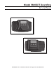
Model 5600SXT Downflow Service Manual IMPORTANT: Fill in Pertinent Information on Page 3 for Future Reference
Table of Contents Job Specification Sheet ......................................................................................................................................... 3 Installation Instructions .......................................................................................................................................... 4 Start-Up Instructions ..............................................................................................................................................
Job Specification Sheet Job Number: __________________ Model Number: ________________ Water Hardness: ___________________ ppm or gpg Capacity Per Unit: ______________ Mineral Tank Size: ___________ Diameter: ___________ Height: Salt Setting per Regeneration: _____________________________________________ 1. Type of Timer: A. 7 Day or 12 Day 2. Downflow: 3. Meter Size: B. Meter Initiated Upflow Upflow Variable A. 3/4” Std Range (125 - 2,100 gallon setting) B.
Installation Instructions WATER PRESSURE: A minimum of 20 psi (1.4 bar) of water pressure is required for regeneration valve to operate effectively. ELECTRICAL FACILITIES: An uninterrupted alternating current (A/C) supply is required. Note: Other voltages are available. Please make sure your voltage supply is compatible with your unit before installation. EXISTING PLUMBING: Condition of existing plumbing should be free from lime and iron buildup.
Start-Up Instructions The water softener should be installed with the inlet, outlet, and drain connections made in accordance with the manufacturer’s recommendations, and to meet applicable plumbing codes. 1. Turn the manual regeneraton knob slowly in a clockwise direction until the program micro switch lifts on top of the first set of pins. Allow the drive motor to move the piston to the first regeneration step and stop.
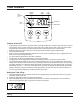
Timer Features Parameter Display Data Display PM Indicator Error/ Information Icon Flow Indicator Service Icon x1000 Indicator Programming Icon Extra Cycle Button Up Button Down Button Features of the SXT: • • • • • • • • Power backup that continues to keep time and the passage of days for a minimum of 48 hours in the event of power failure. During a power outage, the control goes into a power-saving mode.
Timer Features Queueing a Regeneration 1. Press the Extra Cycle button. The service icon will flash to indicate that a regeneration is queued. 2. To cancel a queued regeneration, press the Extra Cycle button. Regenerating Immediately Press and hold the Extra Cycle button for five seconds.
Timer Operation Meter Immediate Control A meter immediate control measures water usage and regenerates the system as soon as the calculated system capacity is depleted. The control calculates the system capacity by dividing the unit capacity (typically expressed in grains/unit volume) by the feedwater hardness and subtracting the reserve. Meter Immediate systems generally do not use a reserve volume.
Timer Operation Control Operation During A Power Failure The SXT includes integral power backup. In the event of power failure, the control shifts into a power-saving mode. The control stops monitoring water usage, and the display and motor shut down, but it continues to keep track of the time and day for a minimum of 48 hours. The system configuration settings are stored in a non-volatile memory and are stored indefinitely with or without line power.
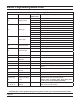
Master Programming Mode Chart Master Programming Options Abbreviation Parameter Option Abbreviation GAL DF VT CT Display Format Valve Type Control Type TS Number of Tanks Tank in Service Gallons Ltr Liters Cu Cubic Meters St1b Standard Downflow/Upflow Single Backwash St2b Standard Downflow/Upflow Double Backwash Fltr Filter UFbF Upflow Brine First 8500 TwinFlo100SXT Othr Other Fd Meter (Flow) Delayed FI Meter (Flow) Immediate tc Time Clock dAY NT Options Day of Week 1 Singl
Master Programming Mode Chart Master Programming Options CD FM K Current Day Flow Meter Type Meter Pulse Setting The Current day of the week t0.7 3/4” Turbine Meter P0.7 3/4” Paddle Wheel Meter t1.0 1” Turbine Meter P1.0 1” Paddle Wheel Meter t1.5 1.5” Turbine Meter P1.5 1.5” Paddle Wheel Meter Gen Generic or Other Meter Meter pulses per gallon for generic/other flow meter NOTES: Some items may not be shown depending on timer configuration.
Master Programming Mode When the Master Programming Mode is entered, all available option setting displays may be viewed and set as needed. Depending on current option settings, some parameters cannot be viewed or set. Setting the Time of Day 1. Press and hold either the Up or Down buttons until the programming icon replaces the service icon and the parameter display reads TD. 2. Adjust the displayed time with the Up and Down buttons. 3.
Master Programming Mode 2. Valve Type (Display Code VT) Press the Extra Cycle button. Use this display to set the Valve Type. The Valve Type setting specifies the type of cycle that the valve follows during regeneration. Note that some valve types require that the valve be built with specific subcomponents. Ensure the valve is configured properly before changing the Valve Type setting. This option setting is identified by “VT” in the upper left hand corner of the screen.
Master Programming Mode 5. Tank in Service (Display Code TS) Press the Extra Cycle button. Use this display to set whether tank one or tank two is in service. This option setting is identified by “TS” in the upper left hand corner of the screen. This parameter is only available if the number of tanks has been set to 2. There are two possible settings: Tank One in Service: Tank Two in Service: U1 U2 6. Unit Capacity (Display Code C) Press the Extra Cycle button. Use this display to set the Unit Capacity.
Master Programming Mode 8. Reserve Selection (Display Code RS) Press the Extra Cycle button. Use this display to set the Safety Factor. Use this display to select the type of reserve to be used in your system. This setting is identified by “RS” in the upper left-hand corner of the screen. The reserve selection parameter is only available if the control type has been set to one of the metered options. There are two possible settings. FS Safety Factor rc Fixed Reserve Capacity 9.
Master Programming Mode 11. Day Override (Display Code DO) Press the Extra Cycle button. Use this display to set the Day Override. This setting specifies the maximum number of days between regeneration cycles. If the system is set to a timer-type control, the day override setting determines how often the system will regenerate. A metered system will regenerate regardless of usage if the days since last regeneration cycle equal the day override setting.
Master Programming Mode 14. Day of Week Settings Press the Extra Cycle button. Use this display to set the regeneration schedule for a system configured as a Day of Week control. The different days of the week are identified as D1, D2, D3, D4, D5, D6, and D7 in the upper left-hand corner of the display. Set the value to “ON” to schedule a regeneration or “OFF” to skip regeneration for each day. Use the Up and Down buttons to adjust the setting as needed.
Master Programming Mode 17. Meter Pulse Setting (Display Code K) Press the Extra Cycle button. Use this display to specify the meter pulse setting for a non-standard flow meter. This option setting is identified by “K” in the upper left-hand corner of the screen. Use the Up and Down buttons to enter the meter constant in pulses per unit volume. 18. End of Master Programming Mode Press the Extra Cycle button to save all settings and exit Master Programming Mode.
User Programming Mode User Programming Mode Options Abbreviation Parameter Description DO Day Override The timer’s day override setting RT Regeneration Time The time of day that the system will regenerate (meter delayed, timeclock, and day-of-week systems) H Feed Water Hardness The hardness of the inlet water used to calculate system capacity for metered systems RC Reserve Capacity The fixed reserve capacity CD Current Day The current day of week NOTES: Some items may not be shown depending
User Programming Mode 5. Press the Extra Cycle button. Use this display to adjust the Fixed Reserve Capacity. This option setting is identified by “RC” in the upper left-hand Corner of the screen. 6. Press the Extra Cycle button. Use this display to set the Current Day of the Week. This option setting is identified by “CD” in the upper left hand corner of the screen. 7. Press the Extra Cycle button to end User Programming Mode.
Diagnostic Programming Mode Diagnostic Programming Mode Options Abbreviation Parameter Description FR Flow Rate Displays the current outlet flow rate PF Peak Flow Rate Displays the highest flow rate measured since the last regeneration HR Hours in Service Displays the total hours that the unit has been in service VU Volume Used Displays the total volume of water treated by the unit RC Reserve Capacity Displays the system’s reserve capacity calculated from the system capacity, feedwater hardne
Diagnostic Programming Mode 6. Press the Up button. Use this display to view the Reserve Capacity. This option setting is identified by “RC” in the upper left hand corner of the screen. 7. Press the Up button. Use this display to view the Software Version. This option setting is identified by “SV” in the upper left hand corner of the screen. 8. Press the Extra Cycle button to end Diagnostic Programming Mode.
Notes Page 23
Control Valve Assembly Page 24
Control Valve Assembly Item No. Quantity Part No. Description 1 ..........................2-4 ........................ 13255 .................................Adapter Clip (Clock or Meter) 2 ..........................5 ........................... 13242 .................................Seal ............................5 ........................... 40628 .................................Seal, 559PE 3 ..........................1 ........................... 61400-12............................
Valve Powerhead Assembly 2 1 4 5 6 7 8 18 9 11 12 17 10 19 14 15 13 3 8 16 1 23 24 25 26A 20 21 22 27 26B 61501-56SE_REVA Page 26
Valve Powerhead Assembly Item No. Quantity Part No. Description 1 ..................... 1 .......................14448-100 ..................Drive Housing Assy, with Pin, 56SXT 2 ..................... 2 .......................12473..........................Screw, Hex Wsh 10-24 x 5/8 3 ..................... 1 .......................19474..........................Harness, Power, 56SXT, Elect 4 ..................... 1 .......................13299..........................Washer, Spring, 3/8 5 .............
3/4” Turbine Meter Assembly Item No. Quantity Part No. Description 1................... 2 .................... 13314 ......................Screw, Hex Washer, 8-18 x 5/8 2................... 2 .................... 19569 ......................Clip, Flow Meter 3................... 1 .................... 19797 ......................Meter Body Assembly, 3/4” Turbine 4................... 4 .................... 13305 ......................O-ring, 119 5................... 1 .................... 19791-01 ..........
Bypass Valve Assembly (Plastic) Item No. Quantity Part No. Description 1................... 2 .................... 13305 ......................O-ring, -119 2................... 2 .................... 13255 ......................Clip, Mounting 3................... 2 .................... 13314 ......................Screw, Hex Washer Head, 8-18 x 5/8 4A ................ 1 .................... 18706 ......................Yoke, Plastic, 1” NPT ............................................ 18706-02 ..............
Bypass Valve Assembly (Metal) Item No. Quantity Part No. Description 1................... 1 .................... 17290 ......................Bypass Valve Body, 3/4” ..................... 1 .................... 17290NP .................Bypass Valve Body, 3/4” Nickel Plated ..................... 1 .................... 13399 ......................Bypass Valve Body, 1” ..................... 1 .................... 13399NP .................Bypass Valve Body, 1”, Nickel Plated 2................... 1 .............
2300 Safety Brine Valve Item No. Quantity Part No. Description 1................... 1 .................... 11942 ......................Brine Valve Body 1/4” NPT 2................... 1 .................... 10138 ......................Ball, 3/8” 3................... 1 .................... 11566 ......................Bull Stop 4................... 1 .................... 10328 ......................Elbow, 1/4” x 1/4” T 5................... 2 .................... 10332 ......................Insert, 3/8” 6......
2310 Safety Brine Valve Item No. Quantity Part No. Description 1................... 1 .................... 19645 ......................Safety Brine Valve Body 2................... 1 .................... 19803 ......................Safety Brine Valve Arm Assembly 3................... 1 .................... 19804 ......................Stud, 10-24 4................... 1 .................... 19805 ......................Nut, 10-24 5................... 1 .................... 19652-01 .................
Troubleshooting Problem Cause Correction 1. Water conditioner fails to regenerate. A. Electrical service to unit has been interrupted A. Assure permanent electrical service (check fuse, plug, pull chain, or switch) B. Timer is defective. B. Replace timer. C. Power failure. C. Reset time of day. 2. Hard water. 3. Unit used too much salt. 4. Loss of water pressure. A. Bypass valve is open. A. Close bypass valve. B. No salt is in brine tank. B.
Troubleshooting Problem Cause Correction 8. Softener fails to draw brine. A. Drain line flow control is plugged. A. Clean drain line flow control. B. Injector is plugged. B. Clean injector C. Injector screen plugged. C. Clean screen. D. Line pressure is too low. D. Increase line pressure to 20 P.S.I. (1.7 bar) E. Internal control leak E. Change seals, spacers, and piston assembly. F. Service adapter did not cycle. F. Check drive motor and switches. 9. Control cycles continuously. A.
Troubleshooting Error Codes Note: Error codes appear on the In Service display. Error Code Error Type Cause Reset and Recovery 0 Cam Sense Error The valve drive took longer than 6 minutes to advance to the next regeneration position Unplug the unit and examine the powerhead. Verify that all cam switches are connected to the circuit board and functioning properly. Verify that the motor and drive train components are in good condition and assembled properly.
Water Conditioner Flow Diagrams Single Backwash Positions Black Cycle Cam (Part Number 17438) Double Backwash Positions Blue Cycle Cam (Part Number 40609) Service Position Service Position 1. Backwash Position 1. First Backwash Position 2. Brine/Slow Rinse Position 2. Brine/Slow Rinse Position 3. Rapid Rinse Position 3. Second Backwash Position 4. Brine Tank Fill Position 4. Rapid Rinse Position Service Position 5.
Water Conditioner Flow Diagrams Backwash Position Brine/Slow Rinse Position Page 37
Water Conditioner Flow Diagrams Second Backwash Position (Double Backwash Units Only) Rapid Rinse Position Page 38
Water Conditioner Flow Diagrams Brine Tank Fill Position Page 39
Wiring Diagram Page 40
Service Instructions Replacing Brine Valve, Injectors and Screen 1. Turn off water supply to conditioner: If the conditioner installation has a “three valve” bypass system, first open the valve in the bypass line, then close the valves at the conditioner inlet and outlet. If the conditioner has an integral bypass valve, put it in the Bypass position. If there is only a shut-off valve near the conditioner inlet, close it. 2.
Service Instructions Timer Replacement To replace timer refer to Replacing Brine Valve, Injectors and Screen, steps 1–3. 1. Remove the control valve back cover. Remove the control valve front cover. Disconnect the meter dome signal wire from the front cover and feed it back through the control. 2. Remove screw and washer at drive yoke. Remove timer mounting screws. The entire timer assembly then lifts off easily. 3. Put new timer on top of valve. Be sure drive pin on main gear engages slot in drive yoke. 4.
Service Instructions Seal and Spacer Replacement To replace seals and spacers, refer to Replacing Brine Valve, Injectors and Screen, steps 1–3. 1. Remove the control valve back cover. Remove the control valve front cover. Disconnect the meter dome signal wire from the front cover and feed it back through the control. 2. Remove screw and washer at drive yoke. Remove timer mounting screws. The entire timer assembly will now lift off easily. Remove end plug retainer plate. 3.
Service Assemblies Air Check 60002-34 ......... Air Check #500 34” Brine Line Flow Controls 60022-12 ........ BLFC .125 gpm 60022-25 ......... BLFC .25 gpm 60022-50 ......... BLFC .50 gpm 60022-100 ....... BLFC 1.0 gpm Brine Line Flow Control Washers 17307............... Washer Flow .125 gpm 12094............... Washer Flow .25 gpm 12095............... Washer Flow .50 gpm 12097............... Washer Flow 1.0 gpm Brine Valve Assembly 60032............... Brine Valve Bypasses 60040...............
Notes Page 45
Notes Page 46
Notes Page 47
P/N 42684 Rev.