
Instruction Manual
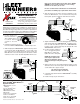

1. Position fender over
tires. Use 2x4 block or
other suitable spacer
to achieve desired
cl ea ra nc e around
tires
Installation Sheet Part Number INS-02023 • 2/02 •Rev. A-8/02 • Rev-B-10/06
Each X-FLEX
®
Multi-Mount
®
T
System Includes:
2 Multi-Mount
®
e-coat
Castings
2 2” sq. X-FLEX
®
Nuts
2 Mounting Tubes
2 Multi-Mount
®
Plates
4 End Caps
2 7/16”-14 x 1-1/4 Bolts
2 7/16” Lock Washer
2 5/8”-11 x 2-1/2” Bolts
2 5/8” Lock Washers
Multi-Mount
®
T
®
NOTE: These instructions for installation are intended to be a
general guide to help the installer. Because of the large number of
possible mounting configurations, the installer is responsible for
the ultimate installation design. Any modifications to the product
are at the discretion, responsibility and risk of the installer.
The adjustable, versatile X-FLEX
®
Multi-Mount
®
T is designed for mounting
on top of the fender using the X-FLEX
®
VIBROWEDGE
®
vibration isolation system.
Assembly Instructions
2. Using the assembly instructions
3. While keeping the VIBROWEDGE
®
and the tube in position
on the fender, slide the Multi-Mount
®
T on the end of the
tube and position it against the truck frame. Rotate the
Multi-Mount to select an existing hole in the frame or drill a
clearance hole for a 5/8” dia. bolt adjustable within 3-1/2”
Note: If you wish to adjust the position of the VIBRO-
WEDGE
®
on the fender to make use of an existing
bolt hole in the frame, do so now.
Be sure to follow truck manufactures recommended
procedures for drilling any required hole in the frame.
4. After the bolt hole has been selected or drilled, loosely
fasten the Multi-Mount
®
T to the truck frame using the
frame plate, square nut and 5/8” bolt with lock washer.
7/16 Lock
Washer
Minimum
1/2"
Truck frame
3" Min. S.A.E.
recommended
clearance
2"x4" spacer
block for desired
clearance
around tires
2" Sq. X-FLEX Nut
Multi-Mount Plate
Casting
5/8 11x 2-1/2
7/16 Lock
Washer
7/16-14 x 1-1/4
Nordlock
Was
her
END CAP
END CAP
MOUNTING
TUBE
X-FLEX
VIBROWEDGE
FENDER
Multi-Mount T
CASTING
TIRE
SPACER
FRAME
FRAME HOLE
Locate in the
3-1/2" Adjustment
Range
X-FLEX
VIBROWEDGE
FENDER
Rotate Multi-Mount T
to an existing hole in
the frame or drill
3-1/2"
ROTATE 360
0
from the X-FLEX
®
VIBROWEDGE
®
, complete steps 1 & 2
TIRE
SPACER
FRAME
FRAME
HOLE
2" Sq. X-FLEX NUT
MULTI-MOUNT PLATE
X-FLEX
VIBROWEDGE
FENDER
Multi-Mount T
CASTING
5. Adjust the Multi-Mount
®
T to the desired position. Proceed
with step #3 & #4 of the VIBROWEDGE
®
assembly instruc-
tions to mark and drill the spot for the VIBROWEDGE
®
Isolators. Then continue with steps #5 through #8 of the
VIBROWEDGE
®
instructions.
6. Position the tube until about
1/2” is showing through the
Multi-Mount
®
clamp, then
tighten the 7/16” clamp bolt.
NOTE: the position of the
tube may be adjusted for
different installations, but the
tube must always be fully through the
clamp.
7. When all the mounts are installed and the fender is in the
desired location, remove the spacer blocks and tighten all
screws and bolts to proper torque:
5/8” bolts torque to 245 ft. lbs.
7/16” bolts torque to 55 ft. lbs.
8. Complete steps #9 & #10 of the VIBROWEDGE
®
assembly
instructions.
9. Install end caps as per instructions.
Installation Sheet
# INS-02023
PATENT #7,073,804