
User guide
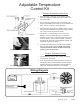

Wiring Diagram
Adjustable Temperature
Control Kit
Assembly & Installation Instructions
1. Attach the temp. control unit to the mounting bracket
using the hardware provided, then push the knob onto
the control shaft.
2. The control can be mounted to any at surface in the
engine compartment that is within 18” of the radiator inlet
hose. Use the 3 mounting screws provided.
3. Insert the temp. sensor thru the radiator core as close to
the inlet hose as possible, then push the rubber insulator
cap over the end of the sensor as shown.
4. Connect the “C” terminal on the control unit to the
positive (+) lead on electric fan unit. For automatic
operation, connect the “2” terminal on the control unit to
a fused positive (+) source that is capable of powering
the electric fan unit (refer to wiring diagram below). Use
the female connectors provided.
5. If manual control is desired, use P/N 31148 / 31148N.
Refer to wiring diagram below. NOTE: If not using
a Flex-a-lite manual switch, DO NOT connect the
ground (-) wire to the switch!
To Adjust Temperature Control
Turn the adjusting knob on the controller completely 1.
clockwise. Idle the vehicle.
When the engine temperature gets above normal, turn 2.
the adjusting knob counterclockwise until fan activates.
Adjusting knob may be adjusted counter-clockwise to
reduce the temperature at which fan a activates.
Insert the temp. sensor near the inlet hose...
Then push the insulator cap over the end of
the sensor.
Rev. 04-15-13 99936
#’s
31148 / 31148N