
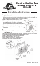
Owners manual
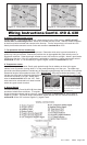

Wiring Instructions Model 410 & 430
Step 1: Locate mounting point for the VSC (variable speed control) unit
Locate a mounting point for the VSC near inlet side of the radiator. The control unit needs to be
placed within about 2' of radiator inlet hose. On the fender well next to the radiator may be a
convenient location. Attach the control unit using the screws provided.
Step 2: Wire the fan motors (refer to Wiring Diagram, below)
Using the large, non-insulated bullet connectors provided, attach a length of the thick (12 AWG) red
wire to the red motor wires at fan. Attach a length of the thick (12 AWG) black wire to the black motor
wires at the fan. Once the fan is in place, these will attach to the control unit. If mounting the control
somewhere in the engine compartment, leave enough wire to reach the control unit.
rev. 11-20-07 98410 Page 2 of 4
NOTE: Models 420 and 440 do not include a fan control unit; skip to page 4 of instructions
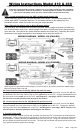
WIRING DIAGRAM - MODEL 430 (PUSHER)
3A. Connect the fan wires to the VSC (Model 410 puller fan only)
Now begin wiring the motors to the VSC. Using the large butt connectors provided, connect the red wire
you attached to the fan motor wires in Step 2 to the yellow wire on the VSC. Connect the black wire from
the motor wires to the purple wire on the VSC. (see Diagram 5 - next page) NOTE: Failure to do this
will result in incorrect operation and damage to fan motors!
3B. Connect the fan wires to the VSC (Model 430 pusher fan only)
Now begin wiring the motors to the VSC. Using the large butt connectors provided, connect the black
wire you attached to the fan motor wires in Step 2 to the yellow wire on the VSC. Connect the red wire
from the motor wires to the purple wire on the VSC. (see Diagram 6 - next page) NOTE: Failure to do
this will result in incorrect operation and damage to fan motors!
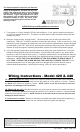
4. Connect power leads
Determine the length needed run thick red and black wire from the VSC to the battery terminals and trim
appropriately. Crimp a large yellow ring connector to one end of the each wire and connect the black wire
to the negative (-) battery terminal, but do not connect the red wire yet. Using butt connectors, connect
the fuse holder provided inline with the red wire. The fuse and fuse holder will protect the fan motors and
your vehicle's electrical system from damage.
FOLLOW THESE INSTRUCTIONS CAREFULLY TO AVOID DAMAGING THE CONTROL
UNIT, FAN MOTORS, AND YOUR VEHICLE! WHEN CRIMPING WIRES, ALWAYS USE
A QUALITY CRIMPING TOOL (DO NOT USE PLIERS OR OTHER DEVICES).
NOTE: If you have purchased a Model 410 fan, procceed to step 3A; If you have purchased a Model 430 fan,
skip step 3A and proceed to step 3B.
WIRING DIAGRAM - MODEL 410 (PULLER)