
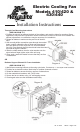
Owners manual
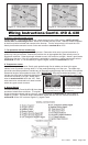

6. Ignition controlled power source
Locate fuse box. Find a circuit that is "hot " when the key is in the "ON" position. NOTE: DO NOT
use the DRL or brake/taillight fuse! Attach the included fuse tap to fuse. Attach a female connector
to the thin red wire included and connect to the fuse tap. Trim the wire so that it will reach the VSC.
Attach pink female connector to end of wire and connect to terminal #9 on VSC.
7. Fan operation with air conditioning
Locate the wires coming from the A/C compressor. Determine which wire is ground and which is
positive by using a volt meter. Connect the positive wire to the supplied thin green wire by use of a
piggyback connector. Determine length needed to reach VSC and trim to length. Attach a pink female
connector to the wire. If the A/C compressor is activated by a positive (+) signal, connect this wire to
terminal #8 on VSC. If it is activated by a negative signal, connect to terminal #7 on VSC.
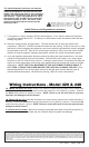
8. Temperature sensor
Locate the temperature sensor. Gently push probe through fins in radiator as close to the upper
radiator hose as possible, leaving about ¼" of the probe protruding out of the core. The rubber cap
should be used when possible to insulate any of the probe coming through the front side of the radiator.
Determine length of wire needed to reach VSC. IMPORTANT: Strip the insulation back about 1" and
fold the wire onto itself to effectively double the thickness of the wire before connecting the pink female
connectors as shown in at right. Attach these
wires to terminals #10 & 11 on the VSC. Both
wires need to be connected but it doesn't matter
which wire goes to each terminal.
9. Manual Switch
If manual switches (Flex-a-lite #31148) have been
purchased, attach them as follows: To override
engine temperature signal and turn fans off, connect the switch to terminal #5 on VSC to send a
negative (-) signal. To override engine temperature signal and turn fans on, connect the switch to
terminal #6 on the VSC so that a negative (-) signal is sent.
When crimping the temp. probe
wires, strip back the insulation,
then fold wire back on itself to
double thickness
Install the temp. probe near the
inlet hose, leaving ¼" of the
probe protruding from the core.
rev. 11-20-07 98410 Page 3 of 4
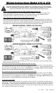
Diagram 5 - Wiring detail for Model 410 fan
Diagram 6 - Wiring detail for Model 430 fan
Wiring Instructions Cont'd. 410 & 430