
Owners manual
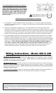

1. Turn ignition on. After 6 seconds, LED #L4 should light up. If not, check to make sure that there
is 12 Volts at terminal #9 on VSC. The delay is to allow starter to start the vehicle without the fans
drawing any power.
2. With your engine running, engage the A/C. The fans should come on and cycle with the A/C
compressor. LED's #L1, L3 and L4 should be lit when fans are running. If they do not turn on, verify
that the A/C clutch is engaged and make sure you have a positive signal when the clutch is engaged
at terminal #8 on the VSC. Shut off A/C and let engine continue to idle, or drive the vehicle a short
distance to bring the engine to operating temperature (monitor the vehicle's temperature gauge).
3. Verify that operating temperature has been reached by feeling the upper radiator hose. Hot water
should be flowing through hose into the radiator. If the fans have not cycled on yet, slowly adjust
the screw on the VSC until the fans cycle on. Turning the screw further in this direction will keep the
engine at a lower temperature, and turning in the opposite direction will keep the engine at a higher
temperature. NOTE: THE TOTAL MOVEMENT OF THE ADJUSTMENT SCREW IS ABOUT ¾
OF A TURN. TURNING THE SCREW BEYOND THE LIMITS WILL DAMAGE THE UNIT! Once
desired temperature is set, let the engine continue to idle and make sure the fans will cycle to
maintain desired temperature. When fans are running, LED's #L1 and L4 should be lit.
Initial Start-up and Adjustment Procedure
The Variable Speed Control has new features.
At the set temperature, the fans will come on
at 60%; this reduces the load on your charging
system. If the temperature rises, the fan speed
will increase. If your set temperature is 195°F,
then between 195° and 205° the fan speed will
increase from 60% to 100%. So after a 10-de
-
gree rise from the set point, the fans will be
running at 100%.
The Flex-a-lite Limited Warranty
Flex-a-lite Consolidated, 7213-45th St. Ct. E. Fife, WA 98424, Telephone No. 253-922-2700, warrants to the original purchasing user, that all Flex-a-lite products to be free of defects in material and
workmanship for a period of 365 days (1 year) from date of purchase. Flex-a-lite products failing within 365 days (1 year) from date of purchase may be returned to the factory through the point of
purchase, transportation charges prepaid. If, on inspection, cause of failure is determined to be defective material or workmanship and not by misuse, accidental or improper installation, Flex-a-lite
will replace the product free of charge, transportation prepaid. Flex-a-lite will not be liable for incidental, progressive or consequential damages. Some states do not allow the exclusion or
limitation of incidental or consequential damages, so the above limitation or exclusion may not apply to you. This warranty gives you specific legal rights and you may have other rights, which vary
from state to state.
The Flex-a-lite warranty is in compliance with the Magnuson-Moss Warranty
Act of 1975.
rev. 11-20-07 98410 Page 4 of 4
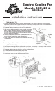
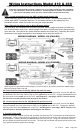
1A. (Model 420 puller fan only): Wire the fan motors to power source (control unit or switch and
relay if desired). Connect the red wires from the fan motors to a 12v. positive (+) source. Connect
the black motor wires to a ground (-) source. NOTE: Failure to do this will result in incorrect
operation and damage to the fan motors!
1B. (Model 440 fan only): Wire the fan motors to a power source (control unit or switch and relay if
desired). Connect the black wires from the fan motors to a 12v. positive (+) source. Connect the red
motor wires to a ground (-) source. NOTE: Failure to do this will result in incorrect operation and
damage to the fan motors!
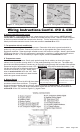
2. Connect the fuse holder. Be sure to connect the provided fuse holder in-line with the positive (+)
power wire to protect the fan motors and your vehicle's electrical system from damage.
Wiring Instructions - Model 420 & 440