Instruction Manual 1
BEFORE CONTINUING WITH THIS INSTRUCTION MANUAL OR ASSEMBLY OF YOUR AIRCRAFT, PLEASE VISIT OUR WIKI SUPPORT SITE FOR THE LATEST PRODUCT UPDATES, FEATURE CHANGES, MANUAL ADDENDUMS AND FIRMWARE OR CONFIG FILE CHANGES FOR THE AURA PROFESSIONAL ADVANCED FLIGHT CONTROL SYSTEM. HTTP://wiki.flexinnovations.
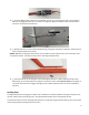
The FlexJet Pro 90 mm combines fast jet performance with modern aerodynamics. The stiff and clean airframe excels at traditional jet aerobatics, while the modern aerodynamics with features such as Leading Edge Root eXtensions (LERX’S), and Dog Tooth leading edges allow an extended angle of attack range. The trailing-link landing gear is forgiving on takeoffs and landings. And the wing spar carries through the fuselage making the aircraft stiff and strong.
(3) 12” servo extension leads , Rx Battery) 1/8” to 3/16” (3-5mm) Striping tape for fan to duct shimming 2-sided mounting tape Hook and loop tape Hook and loop straps Clear vinyl tape Recommended Optional Equipment: Aura 8 AFCS Battery Charger Main Wheels with Brakes 3-axis gyro (FPZAURA08 recommended) ISDT T8 (ISDTT8) Includes brake controller (FPMWB55) Tools: Adhesives: Drill and Bits (1/16” or 1.5mm) Hobby knife Phillips Screwdriver Hex Drivers: 2.
2. 3. 4. 5. 6. 7. 8. In some cases, the written instructions may differ slightly from the photos. In those instances, the written instructions should be considered correct. This model is not a toy, rather it is a sophisticated hobby product and must be operated with caution and common sense. This product requires some basic mechanical ability. Failure to operate this product in a safe and responsible manner could result in injury, or damage to the product, or other property.
Wing and Rudder Assembly NOTE: The ailerons can also be used as flaperons. We will refer to them as ailerons during the assembly process. 1. Use sandpaper to clean up the 3 horns and rough up the gluing area near the base. 2. Open the slots for the 3 control horn in the Ailerons and Rudder. Trial fit and use a sharp #11 hobby knife to carefully remove the covering in the area around the horns as shown. 3. Glue the 3 horns into the 3 surfaces with 15 minute epoxy.
5. Use thin CA to carefully glue each hinge from each side of the wing. Make sure the glue wicks into the slot. Use a tissue to blot away any excess glue. 6. After about 10 minutes re-apply a small amount of thin CA to each hinge and blot away any excess. Let cure and give a good tug (about 8 pounds force) on each control surface to confirm it is secure. 7. Repeat steps 4 to 6 to install the Rudder onto the Fin. The gap at top between the fin and the rudder balance tab is about 2mm. 8.
9. Assemble three linkages as shown. Jam nuts are provided for the clevises. Use blue thread lock on all metal to metal threaded joints to make them secure and to prevent play and thread wear over time. 10. Fit the servo to the servo hatch as shown noting the slot orientation above and just below. Use the correct drill for your servo screws (typically about 1/16” or 1.5mm) to drill the servo mounting holes. Screw the servo to the inside of the hatch using the screws provided with the servos. 11.
13. Connect a 600mm (24”) extension to the Rudder servo and run it through the tube in the fuselage. It will soon be plugged into the Aura or receiver as configured. Tip: Use dental floss with several knots to secure the servo lead to the extension. 14. Repeat steps 10 to 12 to install the Rudder linkage, noting the servo/hatch orientation. (Choose hole in servo arm about 18mm from center.
1. Plug the sequencer can directly into your receivers Channel 5 port. 2. Program the transmitter’s channel 5 to a 2-position switch, and set the travel to about 110% to make sure it passes the switching threshold (you can reverse later based on your preference). 3. With the receiver bound and functioning and the transmitter On, apply the Rx power. The retract switch will need to be cycled once to arm the retracts each time the model is powered up. Cycle the retracts to the UP position.
Equipment Installation: 1. Mount the retract sequencer with 2 sided tape or hook and loop tape. The location above the right air intake is recommended. 2. Mount the receiver and antenna’s according to your manufacturer’s recommendations. We suggest mounting the receiver with hook and loop tape. This will allow access later for installing additional items. 3. Temporarily install the removeable battery tray to aid in locating equipment.
4. If you are using and Aura 8 AFCS, mount it now using the included mounting tape. Never use hook and loop to mount a gyro system. It is not stable enough. The fixed platform at the back of the battery tray is the recommended location. Make the required connections to your receiver. In the final assembly stages you should further secure your Aura with a strap of hook and loop material. Install the Elevator Servos 1. Connect the elevator servo leads to the 600mm (24”) servo extensions.
Install the Stabs and Elevator Linkages 1. A servo arm hole of not longer than 15mm radius should be used. Install the linkages onto the servo arms. 2. Center the servos and install the servo arm. (Do not install the arm center screws yet, as you can remove the arms to adjust the length of the linkages. Be sure to secure the center screws once adjustments are complete). Put threadlock on metal to metal connections ONLY.
TIP: You can install the stab arm and ‘rotate’ the parts to the most vertical position possible while the glue cures. 11. After the epoxy is cured, install the stab to the fuselage using the circular shims as before. 12. Use a toothpick to place three tiny drops of epoxy about the side of the head of a pin equally spaced around the spline of the stab.
Prepare and install the ESC 1. Check the length of the ESC wire and make sure the length can reach from the ESC location to the fan location. Adjust as needed. 2. Install the proper plug-in connectors between the ESC and the Motor. Flex used 4mm bullets on the motor side on the prototypes, the JP supplied bullets are also good. Flex uses EC5 connectors for the Battery to ESC connection. 3.
7. Glue the ESC Mount to the bottom of the battery tray. 8. Double-check that the wiring is sufficient to reach the Fan/Motor. Note that the V-Good 120A ESC is small and can temporarily pass back through the former temporarily for wire connection. 9. Set the parts aside until after the Fan is installed. Install the Aft Inlet Duct and Fan and ESC 1. Remove the fiberglass fuselage tail-cone by removing the (3) 3mm x 12mm SCHS and set the parts aside. 2.
6. Install the Aft Duct through the very back of the fuselage. Sleeve the Aft Duct to the forward duct. (final parts may vary slightly from photo) 7. Fit and install the fan with (2) 3mm x 12mm SHCS with 3mm washers. (Extra holes are provided to aid in accommodating other fans.) 8. Plug the Motor and ESC wires together. The wire basically wraps around from the above (top) the duct at the front, to below (bottom) the duct at the back. 9.
11. We recommend gluing two-sided hook and loop strap to the mount as shown. Then apply thick two-sided foam tape to the mount. 12. Attach the ESC to the mount/tape and secure with the hook and loop strap. 13. Bolt the battery tray into the model with (4) 3mm x 12mm SHCS and (4) 3mm washers. Install the Tailpipe 1. Re-install the fan’s center body fairing (Some users prefer to save the weight and run without it.) 2. Fit the tailpipe over the OUTSIDE of the fan unit.
4. Remove the temporary masking tap and adjust the tailpipe fore and aft until it is flush with the tailcone aft edge. Secure the tailpipe to the fan unit with quality vinyl tape. Install the Ventral Fins and Fan Hatch 1. 2. 3. 4. 5. 6. 7. Test fit the ventral fins on the aircraft using the fixture parts provided. Remove the fins. Use coarse sandpaper to aggressively scuff the sockets in the fuselage. Rough up the corresponding covering on the fins with coarse sandpaper.
Center of Gravity and Receiver Battery Install 1. The CG is located 105mm aft of the front corner of the wing. You can apply a piece of masking tape to the model and mark it on both sides of the fuselage for the balancing process. After first flights, pilots can adjust the CG fore and aft up to 6mm per their preference. 2. Temporarily install your plywood receiver battery mount. 3. With the model completely assembled and the gear down, place your motor battery in the model in a convenient location.
4. Place your receiver battery a bit forward and check the CG of your model. (In our models the Rx battery was placed most of the way forward and hung finally on the ‘bottom’ side of the mount.) 5. You can tune the location of your motor and receiver batteries to obtain convenient and adjustable locations for each of them. 6. Once you have decided where the receiver battery should be located, apply hook and loop tape to the forward receiver battery mount and battery.
The control throws and expo here are a great starting point, you can further adjust to your preference after flying. In typical cases, we recommend Channel 5 for the retracts.
www.flexinnovations.com ©2019 Flex Innovations, LLC. Potenza™ is a trademark or registered trademark of Flex Innovations, LLC. DSM®, DSM2™, and DSMX™ are trademarks or registered trademarks of Horizon Hobby LLC Futaba™ is a registered trademark of Futaba Denshi Kogyo Kabushiki Kaisha Corporation of Japan. Jeti™, UDI, and Jeti Model are trademarks or registered trademarks of Jelen, Ing. Stanislav of Czech Republic Hitec is a trademark or registered trademark of Hitec RCD USA Inc.