
Installation and user manual
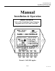


SES Flexcharge USA
1217 State St., Charlevoix MI, 49720
Ph: (231) 547-9430 Fax: (231)547-5522
Page 4
sSCLC Manual.doc
Installation Guide
x Unpack the controller and inspect it for shipping related damage. Do not wear static producing
clothing when handling the uninstalled controller. If possible ground yourself before touching
the terminal connections.
x
12V / 24V Operation
The controller is shipped ready for 12V systems. To select 24V, touch the copper part of the controller’s
black wire and using a small pair of wire cutters, cut the loop of silver wire which protrudes through the
potting material on the back of the controller.
x
Mounting
Mount the Controller where it is protected from direct exposure to weather, and where it will not be
exposed to high vibration (i.e. on an engine block). Generally the ambient temperature should not exceed
about 130°F.
The controller should be mounted within 8 wired feet of the battery bank for best voltage sensing.
CAUTION Ground yourself before touching the wiring to dissipate any static charge. Wear a
ground strap if possible while working on the system.
x Remove the Fuse from your fuse holder prior to making wire connections.
x
Wire Connections. (Standard units are supplied with a terminal strip)
(For custom 30A models with pigtail wires use #10AWG or large gauge wire for connections)
Connect wires from all system grounds (PV-, Load- & Earth Ground) to the battery negative terminal.
Install a BLACK #12AWG (or larger) wire from the battery bank’s negative terminal and install the wire in
the BAT- terminal (or solder it to the controller’s Black wire).
Install a RED #12AWG (or larger) wire from battery bank’s positive terminal to the controller, and install
the wire in the BAT+ terminal (or solder it to the controllers RED wire).
Install a BLUE #18AWG (or larger) wire from the solar panel side of the blocking diode on ONLY ONE of
the solar panels to the controller, and install the wire in the SENSE PV terminal (or solder it to the
controller’s blue wire).
Install an ORANGE #12AWG (or larger) wire from the banded side of the blocking diode of each solar
panel to the controller, and install the wire in the PV+ terminal (or solder it to the controller’s ORANGE
wire).
Install an YELLOW #12AWG (or larger) wire from the Load’s positive input terminal to the controller, and
install the wire in the LOAD+ terminal (or solder it to the controller’s YELLOW wire).
x If you purchased the Temperature Compensation option, place the sensor near or on the battery.
x Install the fuse in your fuse holder.