
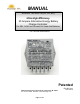
User and installation manual


Page 2 of 23
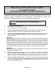
IMPORTANT INFORMATION
THE NC25 CONTROLLER IS AN "ON/OFF" REGULATOR NOT A CONSTANT VOLTAGE
REGULATOR, AND THEREFORE IT CANNOT BE TESTED BY SIMPLY MEASURING THE OUTPUT
VOLTAGE ON THE TERMINAL STRIP OF THE CONTROLLER. THE CONTROLLER MUST BE
CONNECTED AS SHOWN IN ONE OF THE SCHEMATICS BEFORE IT WILL REGULATE.
READ ALL OF PAGES 5 through 8 OF THIS MANUAL TO LEARN HOW THE CONTROLLER
REGULATES BEFORE CONCLUDING THAT YOUR CONTROLLER IS NOT REGULATING.
All wire to wire and crimp connections must be
soldered for this, or any charge controller to
operate dependably.
Do not solder on the controllers terminal block.
The terminals on the controller are coated with an
anti corrosion coating.
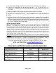
Table Of Contents
Page Contents
1 Cover
2 Table Of Contents
3 Features
4 Controls and Indicators
5 Installation Instructions
7 Indicator Functional Description
8 Flexcharge Energy State Charge Method (ESCM)
9 Operating Characteristics - Wire Selection Chart - Diode Selection Chart
10 Using or Not Using Blocking Diodes
11 Solar Panels Charging One Battery Bank
12 Solar Panels Charging Two Battery Banks
13 Wind/Water Generator Charging One Battery Bank
14 Wind/Water Generator Charging Two Battery Banks
15 Solar with Wind/Water Generator Charging One Battery Bank
16 Solar with Wind/Water Generator Charging Two Battery Banks
17 Charging Two Battery Banks Using a Selector Switch
18 Charging Two Battery Banks Using an A/B Battery Switch (Not Recommended)
19 Charging From Smaller Outboard Motors
20 Expanding the NC25A to Regulate High Ampere Charging Sources
21 Troubleshooting Guide
22 Charging Efficiency Graphs
23 General Guidelines for Designing Your System, and Warranty Information