
User and installation manual


Page 5 of 23
Congratulations, you will soon be using the most efficient controller available. Using this
controller has the direct equivalency of increasing your solar panel capacity by up to 20% over
any other controller Flexcharge
TM
USA has examined. This controller is available with
capacities to 2000 amps with the same, or increased charging efficiencies.
NOTE: The NC25A does not contain any blocking diodes.
IMPORTANT:
PLEASE READ THE SECTION "USING BLOCKING DIODES" Pg.10
1) Choose a good mounting location.
Even though the controller has been designed for mounting outside, mounting it in a more protected
environment will help to extend it's operational life.
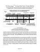
2) Install the NEGATIVE BATTERY SENSE WIRE from the controller's terminal block to the
battery bank negative (-) terminal. You should use #16 to #14 awg black wire.
3) Install the POSITIVE BATTERY SENSE WIRE from the controller's terminal block to a 1A or 2A
fuse and then to the battery bank's positive (+) terminal. You should use #16 to #14 awg
yellow or red wire.
IMPROTANT
When installing the terminals on to the sense wires for connection to the battery, crimp then
solder the terminals to the wire. Make absolutely sure these wires make very good electrical and
mechanical connection with the battery's terminals. If either of this or the ground connections were to
loosen, or corrode, the controller will have no way to sense battery voltage, causing it to switch to a
non-regulating mode and overcharge the batteries. The sense wires may be extended up to 100 feet
using #14 or larger wire. All splice joints must be soldered. If you are charging multiple isolated battery
banks through a battery isolator, connect the SENSE wires to the primary (most used) battery bank.
The other batteries will follow the primary battery's voltage, and will not be over or under charged.
IMPORTANT
For the next four steps, see the Wire Size Table on page 9 to select the correct size wire for your
charging current and length of wire.
4) Connect the charging source negative (-) wire to the negative (-) terminal on the battery
and/or the system's negative battery bus. If you are using a smart battery fuel meter that
measurers total Input to Output Amp/Hours, it will usually have a shunt in the (-) connection to the
battery. Connect the (-) wire from the charging source to the shunt as shown in the meter’s manual.
5) Install the BATTERY POSITIVE (BAT. +) wire from the controller to the battery's positive
terminal. A fuse rated at 1.5 times larger than your maximum charging current, but less than
30A, should be installed in this wire near the battery. Remember to solder all wire connectors
even if they use crimped connectors.
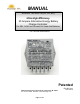
INSTALLATION INSTRUCTIONS
Flexcharge
TM
USA NC25A
ULTRA HIGH EFFICIENCY CHARGE CONTROLLER