5478EN-3 Spiral Elevator Type 5995512 Created by EBCCW 00:06 Created by EBCCW 00:06 96:05 User Manual Original Instructions 2011
Created by EBCCW 00:06 96:05
Spiral Elevator User Manual © Flexlink Components AB 2010 All Rights Reserved No part of this program and manual may be used, reproduced, stored or transmitted in any form or by any means without the written permission of FlexLink Components AB. The contents of this manual are for informational use only. All information and specifications contained in this document have been carefully checked to the best efforts of FlexLink Components AB, and are believed to be true and accurate as of time of publishing.
5478EN-3
Created by EBCCW 00:06 Content 1 Safety ....................................................... 3 5.2 Assembly ................................................29 1.1 System information.................................. 3 5.3 Validation ................................................33 1.2 The most important safety conditions ...... 4 5.4 Integration in a (transport) system .........35 1.3 Description of safety provisions ............... 5 5.5 Setting of the Spiral Elevator..................
Page II of II 5478EN-3
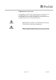
Preface Purpose of this manual The purpose of this manual is to describe various operations that are intended for the user to perform. This document contains remarks that point out a risky or specific situation to the user. In many cases this situation is provided with one of the symbols given below. General warning for danger! . Warning for electrical voltage! . Attention, this is an important notice! .
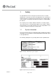
Requirements of the user The Spiral Elevator should only be operated by a person who has become acquainted with section 1 'safety' and trained in the use of the unit. The Spiral Elevator should only be installed by persons who have become acquainted with section 4 'unload the Spiral Elevator. . . Note! Maintenance activities on the Spiral Elevator should only be carried out by a technically qualified person.
Safety 1 Safety The Spiral Elevator has been designed such, that it can be used and maintained in a safe way. This holds for the application, the circumstances and the instructions described in the manual. Any person working with or on this machine should study and follow the instructions contained within this manual. The company or the country in which the machine is used may require extra safety measures. This particularly applies to the working conditions.
Safety 1.2 The most important safety conditions Before the Spiral Elevator is put in to service, the following safety conditions must be met: • Provide good ambient lighting. • Equipment users should have read and understood the operating instructions to operate, maintain or clean the machine. • Equipment users should not reach into the machine while it is running. Even if the machine is not running, it may be 'on', which means it may start operating automatically.
Safety 1.3 Description of safety provisions As a standard the Spiral Elevator is not provided with control or any safety provisions. Before putting the Spiral Elevator into service some safety provisions are to be incorporated. The purpose of these safety provisions is to protect the user, the product and the Spiral Elevator against undesired situations (damage). If these safety provisions are not incorporated it will invalidate the warranty.
Safety Mechanical Remark Height / width detector Product entering the Spiral Elevator should not be of a size where the product can become jammed in the Spiral Elevator. In order to ensure that product cannot become jammed in the Spiral Elevator due to oversize some automatic checks for width and height can be done. This detection must take place before the Spiral Elevator in order to stop the product or Spiral Elevator.
Safety 1.5 Explanation of symbols Pictogram symbols have been placed on the Spiral Elevator in order to identify to the user certain conditions or provide certain information on components of the Spiral Elevator. No. Description Picture 1.Spiral Elevator plate This contains the name and the address of the initial manufacturer, series or type indication, serial number and the year of construction of the Spiral Elevator. 2.
Technical specifications 2 Technical specifications Below is the technical specification of the Spiral Elevator. Further product details to which the Spiral Elevator has been designed are contained within the overall Project Documentation (when purchased as part of a Project System). Use of the Spiral Elevator outside of the scope detailed within the technical specification, quotation or documentation will invalidate the warranty.
Technical specifications 2.1 Technical data 500 mm (inclination) 5000 mm (Max. heigth 8 windings) Lower height 600/700/800/900/1000 mm -50/+70 Machine incl.
Technical specifications 2.
Technical specifications 2.3 Operating conditions The circumstances under which the Spiral Elevator can be operated partly depend on the materials selected. FlexLink has defined a number of parameters within which the Spiral Elevator would be allowed to function. Should the Spiral Elevator still be operated beyond these limiting values, FlexLink cannot guarantee the good functioning of the Spiral Elevator.
Introduction 3 Introduction This section deals with a number of general matters with respect to the Spiral Elevator. This involves, among other things, the purpose of use, the conditions of use and the working principle of the Spiral Elevator. Should you have any further questions on the safe operation of the Spiral Elevator please contact FlexLink. The warranty conditions have been included in the FlexLink quotation or are available separately from FlexLink.
Introduction 3.2 Description of the Spiral Elevator The Spiral Elevator is applied in a (transport) system where products can be transported vertically in a relatively small area. The Spiral Elevator can be coupled to other transport systems and be built according to the customer's needs. A B Figure 3 Principle sketch (Transport direction up) / Configuration options Created by EBCCW 00:06 Before the Spiral Elevator is put in to service a suitable Risk Assessment should be completed.
Introduction Configuration input / output The configuration of the Spiral Elevator is available in different formats with regard to input / output positions. These configuration types are expressed in the letters A or B. A B It is possible to have a configuration with which the output side is placed at a different angle. For any special configurations please contact FlexLink.
Introduction Components Spiral Elevator The Spiral Elevator consists of the following components: 1 2 3 4 5 Created by EBCCW 00:06 Figure 4 Components Spiral elevator 5478EN-3 Page 15 of 68
Introduction No. Component Description 1, 2, 4 and 5 Frame The basic frame of the Spiral Elevator consists of a central column (1), an upper end (2), a lower end (5) and a frame (4) that is attached to the floor surface. The materials of these components depend on the configuration selected. Both the upper end and the lower end may function as the input or output part of the Spiral Elevator. 3.
Introduction General terminology used for the Spiral Elevator parts Central column A B Lower end unit B 6 Upper end unit 1 2 3 4 5 7 8 6 1 Metal chain or transmission chain 2 3 7 Slide rail 4 Sprocket or Sprocket wheel Base frame Created by EBCCW 00:06 Feet 5478EN-3 Bearing for conveyor chain Link Conveyor A 8 Conveyor chain plate, link or slat Page 17 of 68 5 Sprocket or Sprocket wheel Bearing housing with bearing
Introduction 4 3 1 2 1) Conveyor plate 1) Motor 2) Basic chain 2) Drive shaft 3) Link 3) Sprocket wheel 4) Bearing 4) Torque arm Components conveyor chain No. Component Description 1. Conveyor chain plate (slat) Narrow plastic plate provided with a guide roller. Conveyor plates are mounted in a row on the basic chain and so form the transport surface. 2. Metal chain (transmission chain) This is a laterally flexible chain on which the conveyor chain is mounted. 3.
Introduction 3.3 Working principle The purpose of the Spiral Elevator is to transport products / goods vertically to bridge a difference of height.
Introduction In most cases the Spiral Elevator is integrated in to a system. The input / output side of the Spiral Elevator is determined dependent on the system. In the following example, it is assumed that the input is at the lower end of the Spiral Elevator and that the product will bridge a difference in height in order to continue the required transport on the output. Input end Transport of Products Output end 1 The product is transferred onto the input of the Spiral Elevator.
Introduction 3.4 Control units As a standard the Spiral Elevator is delivered without any control system. When a Spiral Elevator is supplied without control it is the responsibility of the system integrator / installer to design a suitable control system. It is preferable to install an isolating switch for the gear motor and it should be of a type able to be padlock off.With this switch the power to the gear motor can be switched / locked off in order to ensure safe working on the Spiral Elevator.
Unload the Spiral Elevator 4 Unload the Spiral Elevator 4.1 Preparation Before starting the unloading, good preparation is required. The appropriate devices must be available. A series of checks must be made to the Spiral Elevator and these should be done: • Before off-loading from the delivery vehicle. • Immediately after off-loading. • Immediately after unpacking.
Unload the Spiral Elevator 4.2 Unloading instructions Initially the Spiral Elevator should be removed from the delivery vehicle by lifting the Spiral Elevator complete with any pallet base and / or packing materials. Before starting unloading, all fastening means (securing belts, screws, etc.) that secure the Spiral Elevator onto the transport vehicle must be removed.
Unload the Spiral Elevator 4.2.1 Erecting the Spiral Elevator This section is for taller Spiral Elevators which are transported in the horizontal position. When putting the unit upright or when moving the Spiral Elevator make sure that the floor is level and clean and has sufficient load carrying capacity. It is generally safer to move the Spiral Elevator to a position close to the final area with the Spiral Elevator remaining on the delivery packing (where applicable).
Unload the Spiral Elevator The following describes a typical method utilizing a hoist • The hoisting device is to be fastened to the cylinder at the top of the Spiral Elevator. Whilst hoisting, the hoist should be well fixed and must not be able to ride/shift away unexpectedly. • Raise the top of the Spiral Elevator around 200mm and stop. • Remove the frame with feet which is temporarily mounted to the Spiral Elevator column top.
Unload the Spiral Elevator . . . • Re-attach the frame with feet, to the final position at the bottom of the Spiral Elevator column. Attach the stay brackets between the Spiral Elevator column and the bottom frames. • Remove feet from the now horizontal position and re-fit in to the other holes in the frame to have the feet in the vertical position. • Check all bolts for the lower frames, feet and stay brackets are in place and secure. • Lower the Spiral Elevator down on to the floor.
Mounting, installation, adjustment 5 Mounting, installation, adjustment This section deals with the installation and adjustments for the Spiral Elevator. The safety conditions detailed in section 1.2 and the Safety Provisions detailed in section 1.3 should be read and understood before installation. 5.1 Provisions to be provided Make sure before integrating that the safety measures detailed in section 1.4 are taken. 5.1.
Mounting, installation, adjustment 5.1.2 Links to adjacent conveyor systems Any additional bracing of the Spiral Elevator in-feed should be provided where necessary. Any additional bracing of the conveyor/process after the Spiral Elevator out-feed should be provided where necessary. With the correct heights set, the distances between the Spiral Elevator ends and the adjacent conveyors / machines can be set.
Mounting, installation, adjustment 5.2 Assembly This paragraph describes a number of operations for Spiral Elevators that are not delivered fully assembled. After having finished mounting the Spiral Elevator, the Spiral Elevator can be integrated (Section 1.4) in a system. 5.2.1 Motor The gear motor may be delivered separately with the Spiral Elevator and then has to be mounted on site.
Mounting, installation, adjustment (Note: The conveyor and gear motor shown are not necessarily the same type as supplied.) • In the correct orientation, slide the gear motor on the shaft up till the locking ring (aligning the keyway to key). • Attach the torque arm to the Spiral Elevator drive end. • Fasten the shaft to the motor with bolt and washer inside the gear motor hollow shaft and place the cover to protect the opening (if cover is applicable).
Mounting, installation, adjustment 5.2.2 Mounting Guide rail components The basic Spiral Elevator does not include guide rail or brackets. Along the sides of the conveyor track are M8 tapped holes typically every 45º to allow brackets to be attached. The following describes how a typical FlexLink Guide Rail Bracket system can be used on the Spiral Elevator. For final detail of the optimum guide rail and bracket arrangement consult the Spiral Elevator supplier or FlexLink.
Mounting, installation, adjustment Procedure for fitting a typical guide rail Attach the Guide Rail Brackets to the frame. If an offset has been chosen, any distance piece has to be placed between the frame and the Guide Rail Bracket. The bolts used to attach the brackets to the conveyor sides should be M8. The length of bolt depends upon the guide rail bracket arrangement used, but should not protrude in to the beam profile by more than 10mm.
Mounting, installation, adjustment 5.3 Validation Initially the validation checks should be for visual condition and dimensions. Subsequently a short test run should be made with the Spiral Elevator in an un-loaded condition. 5.3.1 Dimension check Spiral Elevator The technical specification and / or relevant drawing can be used for the dimension check. 5.3.
Mounting, installation, adjustment Test Procedure No. Test Checks Duration 1. Run the Spiral Elevator for very short duration (at 10 Hz if variable speed motor). Check the Spiral Elevator for the rotation direction of the conveyor chain. If this is not correct, then make necessary adjustments to the electrical control circuit or system. 2. Run the Spiral Elevator (run at 10 Hz if variable speed motor).
Mounting, installation, adjustment 5.4 Integration in a (transport) system The Spiral Elevator is a machine that is integrated in a system of conveyors. This means that an input and output are to be connected to it. If the Spiral Elevator is to be fitted into an existing situation, this usually gives more problems with the installation than in a completely new situation. 5.4.
Mounting, installation, adjustment 5.4.2 Checklist integration After the integration the checklist given below should be completed to ensure a satisfactory integration. No. Component Remark Checked 1.
Mounting, installation, adjustment 5.5 Setting of the Spiral Elevator The mechanical and control setting for the Spiral Elevator need to be done correctly, with particular regard to the ends and transfers to ensure good operation. 5.5.1 Mechanical Mechanically there are a number of items which can be set for the Spiral Elevator. The general items are detailed below . Tools No. Component Setting / Remark 1.
Mounting, installation, adjustment 5.5.2 Controls The table below gives some general guidelines with regard to the control system used to operate the Spiral Elevator. . No. Component Setting Remark 1. Frequency control (where fitted) 15% The speed difference of the feeding conveyor to the Spiral Elevator or the Spiral Elevator to the receiving conveyor should generally be below the setting value.
Mounting, installation, adjustment 5.6 Test run - partially loaded In this paragraph the Spiral Elevator will be checked in a semi-loaded condition with all safety provisions activated. If during the test run any of the following situations occur, the test must be stopped and the Spiral Elevator must not be tested further until the issue has been solved.
Mounting, installation, adjustment No. Check Remarks Passed 3. Are any conveyor chain plates moving unexpectedly at any position throughout the Spiral Elevator? This may occur if there are some loose conveyor plates (see Section 6.3 on page 57). Yes / No 4. Are there any conveyor chain plates which are raised at any position? This may occur because conveyor plates are loose or the reversing rollers or a sprocket wheel are not aligned well (see Section 6.3 on page 57). Yes / No 5.
Created by EBCCW 00:06 Mounting, installation, adjustment No. Check Remarks Passed 11. Is the product properly transported throughout the Spiral Elevator. Generally the product will not twist whilst travelling up or down the Spiral Elevator. If undue twisting does occur, discuss this with the supplier. Yes / No 12. Are there any protrusions or irregularities along the guide rail? The product should not stick or jam against the guide rail.
Mounting, installation, adjustment Check (safety) provisions The basic Spiral Elevator supplied by FlexLink does not include any additional safety provisions such as isolators, stop/start devices, emergency stopping systems or guards at the in-feed / out-feed ends. Any issues with regard to the safety items should be investigated and discussed with the designer of the control and safety system. Below is a check list for some general safety items. No. Check Remarks Passed 1.
Technical maintenance 6 Technical maintenance Technical maintenance is an important part of this manual. Good maintenance will prolong the life of the Spiral Elevator and help to reduce any costs resulting from breakages or downtime. This section includes a troubleshooting list in section 6.3 and a maintenance schedule in section 6.4. Before any maintenance functions are carried out on the Spiral Elevator the power supply to the gear motor must be safely isolated. 6.1 Check and control procedures 6.1.
Technical maintenance 6.1.2 Checking chain tension and chain stretch The conveyor chain of the Spiral Elevator must have the correct tension. If the tension is not correct, the following may occur: • Chain runs off the sprocket (jumps a cog). • Conveyor plates grab into the return track causing them to break or become loose from the chain. • Excessive wear of the end sprocket caused by too high tension. In order to prevent these problems, it is necessary to regularly check the chain tension.
Technical maintenance Procedure to check chain stretch • Make sure that the main switch has been switched off, and safely isolated. • At a position on the idler or drive end of the Spiral Elevator, stretch at least 8 conveyor chain plate links apart. • Measure the distance between the start of plate 1 and the start of slat 8 (i.e. the pitch across 7 conveyor chain plates - see picture). For a new chain this distance is 267 mm [10,5"]. • The maximum allowed chain stretch is 1.5%.
Technical maintenance 6.1.3 Checking guide rail Products that are transported over the Spiral Elevator can make contact with the guide rail. A stoppage may damage the guide rail. This may later result in products getting stuck at the damaged place and therefore it is important that the guide rail is regularly checked for irregularities and is adjusted or repaired if necessary. 6.1.
Technical maintenance 6.2 Maintenance procedures It's strongly recommended to perform maintenance activities according to the methods described. During maintenance proper and safe tools must be used. Before disassembling any part please refer to the assembly section in this manual. 6.2.1 To move the conveyor chain Follow the below procedure to move the conveyor chain within the Spiral Elevator: . Created by EBCCW 00:06 .
Technical maintenance 6.2.2 Replacing conveyor plates(slats) This paragraph explains how to replace a broken or missing conveyor plate (slat). Note! If a conveyor plate is incorrectly mounted damage to the Spiral Elevator and the products transported on it may result. . Danger: Make sure that the main switch has been switched off, and safely isolated. . Follow the below procedure to replace a conveyor plate (slat): • The slat can be replaced best at the lower end of the Spiral Elevator.
Technical maintenance • Apply force on the middle of the slat so that it clicks onto the chain. You can possibly use a rubber mallet for this. Repeat this procedure if more than one slat needs to be placed. Figure 13 Placing a slat • . . . . Created by EBCCW 00:06 . 5478EN-3 After maintenance on the conveyor chain test run the machine at 10% of the speed and check if the conveyor chain runs correctly.
Technical maintenance 6.2.3 Shorten chain If the conveyor chain stretch exceeds the limit (see Section 6.1.2 on page 44) the chain must be shortened. Shortening the chain can best be done at the lower end. FlexLink delivers a chain tensioner with the machine to assist in this procedure. Procedure to shorten the chain: Figure 14 Working room at lower end • Every 5 m [16' 5"] the metal chain is connected with 2 connecting links. The slats located above these links are marked with two red dots.
Technical maintenance 6.2.4 Align sprocket wheel If the conveyor chain does not run smoothly or is noisy, one of the sprocket wheels at the conveyor ends may not be aligned correctly. This may cause extra wear of chain and sprocket wheel. Tools Procedure to align sprocket wheel at lower or upper end Created by EBCCW 00:06 Figure 17 Lower end 5478EN-3 • Move the conveyor plate with the coloured dot to the lower or upper end.
Technical maintenance 6.2.5 Replace sprocket wheel, upper end Find the conveyor plate with a coloured dot marked on it and move this conveyor plate to the upper end of the Spiral Elevator. Under this conveyor plate there is a locking link that can easily be removed. Tools Danger: Make sure that the main switch has been switched off, and safely isolated. . Procedure Figure 20 Dismounting of bolt • Remove the conveyor plate with the coloured dot.
Technical maintenance • Once the gear motor has been removed, the grub screw in the locking rings of the bearing blocks can be loosened. The bearing blocks can then be removed and slid off of the ends of the shaft. • The shaft with sprocket wheel can then be removed from the end unit. Figure 23 Bearing block with locking Figure 24 Shaft with sprocket wheel ring Note! The shaft and sprocket are removed as one piece. These can be replaced as one piece or as individual items.
Technical maintenance 6.2.6 Replace sprocket wheel, lower end Find the conveyor plate with a coloured dot marked on it and move this conveyor plate to the lower end of the spiral conveyor. Under this conveyor plate there is a locking link that can easily be removed. Tools Danger: Make sure that the main switch has been switched off, and safely isolated . Procedure • Figure 25 Dismounting of slide rails Remove the conveyor plate with the coloured dot.
Technical maintenance Note! The shaft and sprocket are removed as one piece. These can be replaced as one piece or as individual items. If replaced as individual items make note of the orientation of the sprocket wheel on the shaft. Created by EBCCW 00:06 . 5478EN-3 • Re-fitting is the reverse procedure of the removal. • After assembly the spiral elevator must be set up (section 5.3.2) and then test run (section 5.6) to check that all items are satisfactory.
Technical maintenance 6.2.7 Lubricate the motor The lubrication of the Spiral Elevator gear motor should lead to a continuous good functioning of the machine. The oil level of the motor is to be checked regularly. • For details of the oil type see the motor specification plate or the documentation from the supplier of the Spiral Elevator or the supplier of the gear motor. • For details of the oil fill quantity and oil level refer to the gear motor manufacturer.
Technical maintenance 6.3 No. Trouble Possible cause Solution 1. Spiral Elevator does not work No power (volts) at the gear motor The cause for lack of power to be investigated by qualified personnel. Gear motor defective Replace the motor Teeth on the sprocket wheel worn Replace the sprocket wheel. 2. Created by EBCCW 00:06 3.
Technical maintenance No. Trouble Possible cause Solution 4. Product stops as a result of defective conveyor plates Missing or defective conveyor plate. Replace conveyor plate (see Section 6.2 on page 47). 5. Product stops at beginning or end of Spiral Elevator Product orientation Check cause of products incorrect orientation. Defective transition roller arrangement (if fitted) Contact the supplier of the FlexLink Spiral Elevator.
Technical maintenance No. Trouble Possible cause Solution 8. Transfer of product on to or off of spiral elevator is poor (depending upon product & specification, the actual transfer may vary). Product stoppage Repair the transfer unit if faulty Product load too high Check the technical specification for the maximum product weight and contact the supplier. Transfer unit not aligned correctly. Align the transfer unit. Transfer unit dirty Clean the transfer unit.
Technical maintenance 6.4 Maintenance schedule Spiral Elevator The FlexLink Spiral Elevator generally requires relatively little maintenance. The list below details the general maintenance operations which must be carried out at the normal time intervals for those maintenance operations. The maintenance intervals are for a Spiral Elevator operating in normal conditions with single shift working (8 hours per day) and in a normal environment.
Technical maintenance Maintenance schedule Spiral Elevator No. Execution Interval Remark 1. Clean conveyor Monthly Regular cleaning depends on product and environment 2. Check the conveyor chain for broken or missing conveyor plates, replace if necessary Daily It is the task of the operator to check this daily (see user’s manual) 3. Check the chain tension Monthly Remove a link if the chain is 38.5 mm too long. If more than two links at the same time are to be removed, contact the supplier.
Put out of commission 7 Put out of commission Decommissioning should be undertaken in a safe and controlled manner. This section details the items which must be done for this decommissioning. 7.1 Disconnect the power sources The main power isolator must be turned off and 'locked off' or power permanently removed from the isolator. If the isolator is mounted on the Spiral Elevator the power supply must be permanently removed from the isolator.
Put out of commission 7.3 Transport While transporting the Spiral Elevator a number of safety measures are to be taken. Use the same tools and equipment as indicated in section 4 for the Unload of the Spiral Elevator. A suitable Method Statement and Risk Assessment for the dismantling and transportation should be done by the relevant responsible person. This Method Statement should be followed throughout the decommissioning process. . Created by EBCCW 00:06 .
Put out of commission 7.4 Disposal If the Spiral Elevator is to be disposed of, then all current regulations for the country and local authorities must be adhered to. The main materials within the spiral elevator can vary depending upon the design of the Spiral Elevator and any accessories attached to the Spiral Elevator (such as guide rail parts). The following lists the general materials within the Spiral Elevator but is not a total list: 7.
Spare parts list A 10 8 Spare parts list 8.
Supplier’s information 9 Supplier’s information This document was drawn up by: FlexLink Components AB Date: 2010/08/23 Copyright: FlexLink Sweden, 2010 The machine was produced/ supplied by: Flexlink Components AB Tel: +46 (0)31-337 31 00 SE-415 50 Göteborg Fax: +46 (0)31-337 31 95 Sweden E-mail: info@flexlink.se www.flexlink.com and Local FlexLink Systems supplier . Note! In case of failures please contact the system integrator.
Manufacturer’s declaration 10 Manufacturer’s declaration The Spiral Elevator is supplied to be incorporated within an overall transport system and is not intended to be used as a stand alone piece of equipment. Therefore a Certificate of Incorporation is applicable for the unit. Created by EBCCW 00:06 Any Certificate of Incorporation will be contained within the separate documentation supplied with the Spiral Elevator or overall system.
Manufacturer’s declaration Page 68 of 68 5478EN-3