
User guide


2 TB 98-01-03
Assembly
1 Cut the three beams to the correct length. Note!
The beams are delivered in lengths of 3020±3 mm.
The length of the assembled XB beam must not be
shorter than 500 mm or exceed 3000 mm.
The lengths of the beams should not differ more
than ±0,5 mm, so they should all be cut at the
same time! (The beams can also be cut after as-
sembly.)
2 Use an idler end unit as a mounting fixture, to en-
sure that the beams are correctly positioned hori-
zontally and vertically.
3 Mount the three beams on to the idler unit. Loosely
tighten one set screw per connecting strip.
4 Insert the correct number of clips from the opposite
beam end. Position them at regular intervals along
the beam profile. (See below)
5 Use the aluminium clip tool to press the two clips
closest to the idler unit together.
6 Loosen the connecting strip set screws and move
the idler unit to the other end of the beam. The set
screws do not need to be tightened.
7 Press the remaining clips together.
8 Remove the idler unit.
9 Use a set-square to check that the beam ends are
perpendicular to the beam side.
10 Cut the beam to the correct length, if this was not
done prior to assembly.
Note!
To simplify the assembly of XB beams, two idler end
units can be used instead of one. The second idler unit
is then placed at the second beam end once all clips
have been inserted into the beam. If two idler units are
used, step 6 can be ignored.
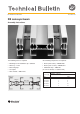
A) If L = 500–800, the distance A should be
150±10 mm, if L = 801–3000, the distance A should
be 250 mm.
A
L
1
82
A
B