Bend Sensor® Technology Electronic Interface Design Guide www.flexpoint.
Contents Page Bend Sensor® Description 3 Bend Sensor® Voltage Divider 4 Adjustable Buffers 5 Bend Sensor® LED Display Demo 6 Multi-channel Bend Sensor® to Digital Interface 7 Bend Sensor® Variable Deflection Threshold Switch 8 Bend Sensor® Variable Deflection Threshold Relay Switch 9 Bend Sensor® Resistance to Voltage Converter 10 Additional Bend Sensor® Resistance to Voltage Converters 11 Bend Sensor® LED Brightness 12 Bend Sensor® Measurement using a Cypress PSoC 13 Bi-directional Be
Introduction This Design Guide is designed to help electrical designers build interfaces that result in the successful integration of Bend Sensor® components into products. Flexpoint Inc. has successfully developed and marketed products incorporating Bend Sensor® products. Most successful Bend Sensor® interfaces start with the same building blocks. This Design Guide comprises a collection of circuits that effectively empower the designer to modify and build customized circuits that complement their product.
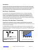
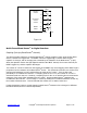
5 v+ Vout (V) 4 Bend Sensor RM + - + v 1K 3K 3 4.7K 10K 2 30K VOUT 1 0 0 0.2 0.4 0.6 Deflection (in.) 0.8 1 Deflection vs. Voltage Figure 1.0 ® Bend Sensor Voltage Divider: For a simple deflection-to-voltage conversion, the Bend Sensor® device is tied to a resistor RM in a voltage divider configuration. The output is described by the equation: VOUT = (V+) / [1+ RM / RBend Sensor®] In the shown configuration, the output voltage increases with increasing deflection.
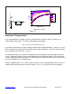
v+ Bend Sensor RM + - + v R3 R1 R2 VOUT v + R5 Bend Sensor v+ RM + - VOUT R4 R6 + - R5 v- Figure 1.1 Figure 1.2 Adjustable Buffers: Similar to the unity gain buffer, these interfaces isolate the output from the high source impedance of the Bend Sensor® device. These alternatives allow adjustment of the output offset and gain. In Figure 1.1, the ratio of resistors R2 and R1 sets the gain of the output.
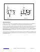
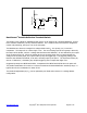
v+ 3 v+ LED1 v+ 10 11 6 12 RHI 13 RM 14 IN 15 R1 OUT 16 Bend Sensor 17 RLO 18 GND REF 1 Figure 1.3 Flexpoint LED Display Demo for Bend Sensor® Device ® Bend Sensor LED Display Demo: This simple Bend Sensor® LED display demo uses a display driver to translate an analog input into ten separate voltage levels. As each level is attained, current is drawn through an LED, lighting it. Consecutive LEDs in a bank are lit as the input voltage goes from high to low.
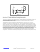
A1 Calibration Channels A2 RMIN RMAX A3 Bend Sensor Selection Channels Bend Sensor A4 Bend Sensor RESET AN-1 INPUT AN 68HC05C4 Microcontroller C1 Figure 1.4 ® Multi-Channel Bend Sensor -to-Digital Interface: Sampling Cycle (any Bend Sensor ® channel): The microcontroller switches to a specific Bend Sensor® channel, toggling it high, while all other Bend Sensor® channels are toggled low.
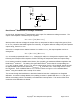
v+ Bend Sensor RM R2 + U1 - VOUT R3 v+ R1 Figure 1.5 ® Bend Sensor Variable Deflection Threshold Switch: This simple circuit is ideal for applications that require on-off switching at a specified deflection, such as touch sensitive membrane, cut-off, and limit switches. For a variation of this circuit that is designed to control relay switching, see Figure 1.6 on the next page. The Bend Sensor® device is arranged in a voltage divider with RM. An op-amp, U1, is used as a comparator.
v+ v+ Bend Sensor RM Relay R3 + U1 - v+ R1 D1 Q1 R2 Figure 1.6 ® Bend Sensor Variable Deflection Threshold Relay Switch: This circuit is a derivative of the simple Bend Sensor® Variable Deflection Threshold Switch of Figure 1.5 on the previous page. It has use where the element to be switched requires higher current, like automotive and industrial control relays. The Bend Sensor® device is arranged in a voltage divider with RM. An op-amp, U1, is used as a comparator.
Bend Sensor vREF RG U1 + VOUT Figure 1.7 ® Bend Sensor Resistance-to-Voltage Converter: In this circuit, the Bend Sensor® potentiometer is the input of a resistance-to-voltage converter. The output of this amplifier is described by the equation: VOUT = VREF * [-RG / RBend Sensor®] With a positive reference voltage, the output of the op-amp must be able to swing below ground, from 0V to -VREF, therefore dual sided supplies are necessary.
Bend Sensor vREF RG U1 + RG VOUT VREF/2 Figure 1.8 U1 + Bend Sensor VOUT VREF/2 Figure 1.9 ® Additional Bend Sensor Resistance-to-Voltage Converters: These circuits are slightly modified versions of the resistance-to-voltage converter detailed on Figure 1.7. Please see Figure 1.7 on the previous page for more detail. The output of Figure 1.8 is described by the equation: VOUT = VREF/2 * [1 - RG/RBend Sensor®] The output swing of this circuit is from (VREF/2) to 0V.
® Bend Sensor Linear Circuit: Figure 1.10 The output of Figure 1.10 is described by the equation: VOUT = VREF/2 * [1 + RBend Sensor®/ RG] ® Bend Sensor Device LED Brightness: For applications where some visual feedback is desired, this circuit is useful. Starting with the basics of the voltage divider, this circuit adds an LED that brightens with increasing deflection. The resistor RL limits the current through the LED. The transistor controls the current through the LED.
® Bend Sensor Measurement using a Cypress PSoC Microcontroller: Cypress Semiconductor has a unique microcontroller that has a current DAC. When used in the circuit above the current source sinks current through the Bend Sensor® and generates a voltage across it which can be measured by the ADC. The current DAC also acts like a variable gain amplifier in the circuit which can be adjusted to make sure that the voltage across the Bend Sensor® is always within the range of the ADC.
® Bi-directional Bend Sensors : Flexpoint also makes Bi-directional Bend Sensors®. When bent in one direction one sensor increases in resistance while the other decreases in resistance. This allows for deflection to be measured in either direction. Bi-directional Bend Sensors® share one common pin. Therefore they can be measured individually using many of the above methods as long as the common pin can be tied to VREF or ground.
Summary: There are many methods that can accomplish the successful implementation of the Bend Sensor® product into an application. Further it is important to consider the mechanical application of the sensors. For information regarding the placement of the sensor into your system refer to the Bend Sensor® Technology Mechanical Application Design Guide. Please contact Flexpoint Sensor Systems @ 801-568-5111 if you have any questions or if e-mail is preferred, contact us at info@flexpoint.com. www.flexpoint.