
Guide


www.flexpoint.com Copyright
©
2015 Flexpoint Sensor Systems Page 10 of 15
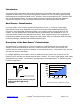
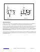
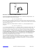
Bend Sensor
v
REF
V
OUT
-
+
R
G
U1
Figure 1.7
Bend Sensor
®
Resistance-to-Voltage Converter:
In this circuit, the Bend Sensor
®
potentiometer is the input of a resistance-to-voltage converter. The
output of this amplifier is described by the equation:
V
OUT
= V
REF
* [-R
G
/ R
Bend Sensor®
]
With a positive reference voltage, the output of the op-amp must be able to swing below ground, from
0V to -V
REF
, therefore dual sided supplies are necessary. A negative reference voltage will yield a positive
output swing, from 0V to +V
REF
.
Since this is a simple inverse relation between V
OUT
and R
Bend Sensor®
, the output equation can be re-
arranged to:
V
OUT
= (-R
G
* V
REF
) / R
Bend
Sensor®
V
OUT
is inversely proportional to R
Bend Sensor®
. Changing R
G
and/or V
REF
changes the response slope. The
following is an example of the sequence used for choosing the component values and output swing:
For a human-to-machine variable control device, like a joystick, the maximum deflection applied to the
Bend Sensor
®
is about 2”. The testing of a typical Bend Sensor
®
shows that the corresponding R
Bend
Sensor®
at 2” is about 4.6 kΩ. If V
REF
is -5V, and an output swing of 0V to +5V is desired, then R
G
should
be approximately equal to this minimum R
Bend Sensor®
. R
G
is set at 4.7 kΩ. A full swing of 0V to +5V is
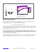
thus achieved. A set of DEFLECTION vs. V
OUT
curves is shown on Figure 1.0 for a standard Bend
Sensor
®
using this interface with a variety of R
G
values.
The current through the Bend Sensor
®
should be limited to less than 1 mA/square cm of applied
deflection. As with the voltage divider circuit, adding a resistor in parallel with R
Bend Sensor®
will give a
definite rest voltage, which is essentially a zero-deflection intercept value. This can be useful when
resolution at low deflections is desired.