
Guide


www.flexpoint.com Copyright
©
2015 Flexpoint Sensor Systems Page 11 of 15
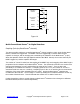
Bend Sensor
v
REF
-
+
R
G
U1
V
OUT
V
REF/2
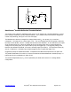
Bend
Sensor
-
+
R
G
U1
V
OUT
V
REF/2
Figure 1.8 Figure 1.9
Additional Bend Sensor
®
Resistance-to-Voltage Converters:
These circuits are slightly modified versions of the resistance-to-voltage converter detailed on Figure 1.7.
Please see Figure 1.7 on the previous page for more detail.
The output of Figure 1.8 is described by the equation:
V
OUT
= V
REF
/2 * [1 - R
G
/R
Bend Sensor®
]
The output swing of this circuit is from (V
REF
/2) to 0V. In the case where R
G
is greater than R
Bend Sensor®
,
the output will go into negative saturation.
The output of Figure 1.9 is described by the equation:
V
OUT
= V
REF
/2 * [1 + R
G
/R
Bend Sensor®
]
The output swing of this circuit is from (V
REF
/2) to V
REF
. In the case where R
G
is greater than R
Bend Sensor®
,
the output will go into positive saturation.
For either of these configurations, a zener diode placed in parallel with R
G
will limit the voltage built up
across R
G
. These designs yield one-half the output swing of the previous circuit, but only require single
sided supplies and positive reference voltages.
Suggested op-amps are LM358 and LM324.