
Guide


www.flexpoint.com Copyright
©
2015 Flexpoint Sensor Systems Page 12 of 15
Bend Sensor
®
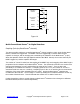
Linear Circuit:
Figure 1.10
The output of Figure 1.10 is described by the equation:
V
OUT
= V
REF
/2 * [1 + R
Bend Sensor®
/ R
G
]
Bend Sensor
®
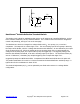
Device LED Brightness:
For applications where some visual feedback is desired, this circuit is useful. Starting with the basics of
the voltage divider, this circuit adds an LED that brightens with increasing deflection. The resistor RL
limits the current through the LED. The transistor controls the current through the LED. Since the circuit
depends on the hfe of the transistor, sensitivity may need to be tuned to accommodate the hfe spread of
common transistors.
Bend Sensor
v
OUT
v
+
R
M
R
L
2N3904