
Guide


www.flexpoint.com Copyright
©
2015 Flexpoint Sensor Systems Page 4 of 15
Bend Sensor
R
M
v
+
V
OUT
v
+
+
-
0
1
2
3
4
5
0 0.2 0.4 0.6 0.8 1
De fle ctio n ( in.)
Vout (V)
1K
3K
4.7K
10K
30K
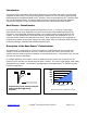
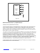
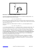
Deflection vs. Voltage
Figure 1.0
Bend Sensor
®
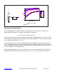
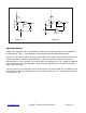
Voltage Divider:
For a simple deflection-to-voltage conversion, the Bend Sensor
®
device is tied to a resistor R
M
in a
voltage divider configuration. The output is described by the equation:
V
OUT
= (V+) / [1+ R
M
/ R
Bend Sensor®
]
In the shown configuration, the output voltage increases with increasing deflection. If R
Bend Sensor®
and
R
M
are swapped, the output swing will decrease with increasing deflection. These two output forms are
mirror images about the line V
OUT
= (V+) / 2.
The measuring resistor, R
M
, is chosen to maximize the desired deflection sensitivity range and to limit
current. Suggested op-amps for single sided supply designs are LM358 and LM324. FET input devices
such as LF355 and TL082 are also good. The low bias currents of these op-amps reduce the error due to
the source impedance of the voltage divider.
A family of DEFLECTION vs. V
OUT
curves is shown in Figure 1.0 for a standard Bend Sensor
®
device in a
voltage divider configuration with various R
M
resistors. A (V+) of +5V was used for these examples.